# Catalyst2: Artifacts on Processes Boundaries
**URL:** https://discourse.paraview.org/t/catalyst2-artifacts-on-processes-boundaries/13489
**Category:** In Situ Support
**Tags:** catalyst
**Created:** [December 12, 2023, 7:27pm UTC](https://discourse.paraview.org/t/catalyst2-artifacts-on-processes-boundaries/13489 "2023-12-12T19:27:39Z")
**Posts on this page:** 5
**Page:** 1
### Author:  [@cartagena](https://discourse.paraview.org/u/cartagena)
#### Post date: [December 12, 2023, 7:27pm UTC](https://discourse.paraview.org/t/catalyst2-artifacts-on-processes-boundaries/13489/1 "2023-12-12T19:27:39Z")
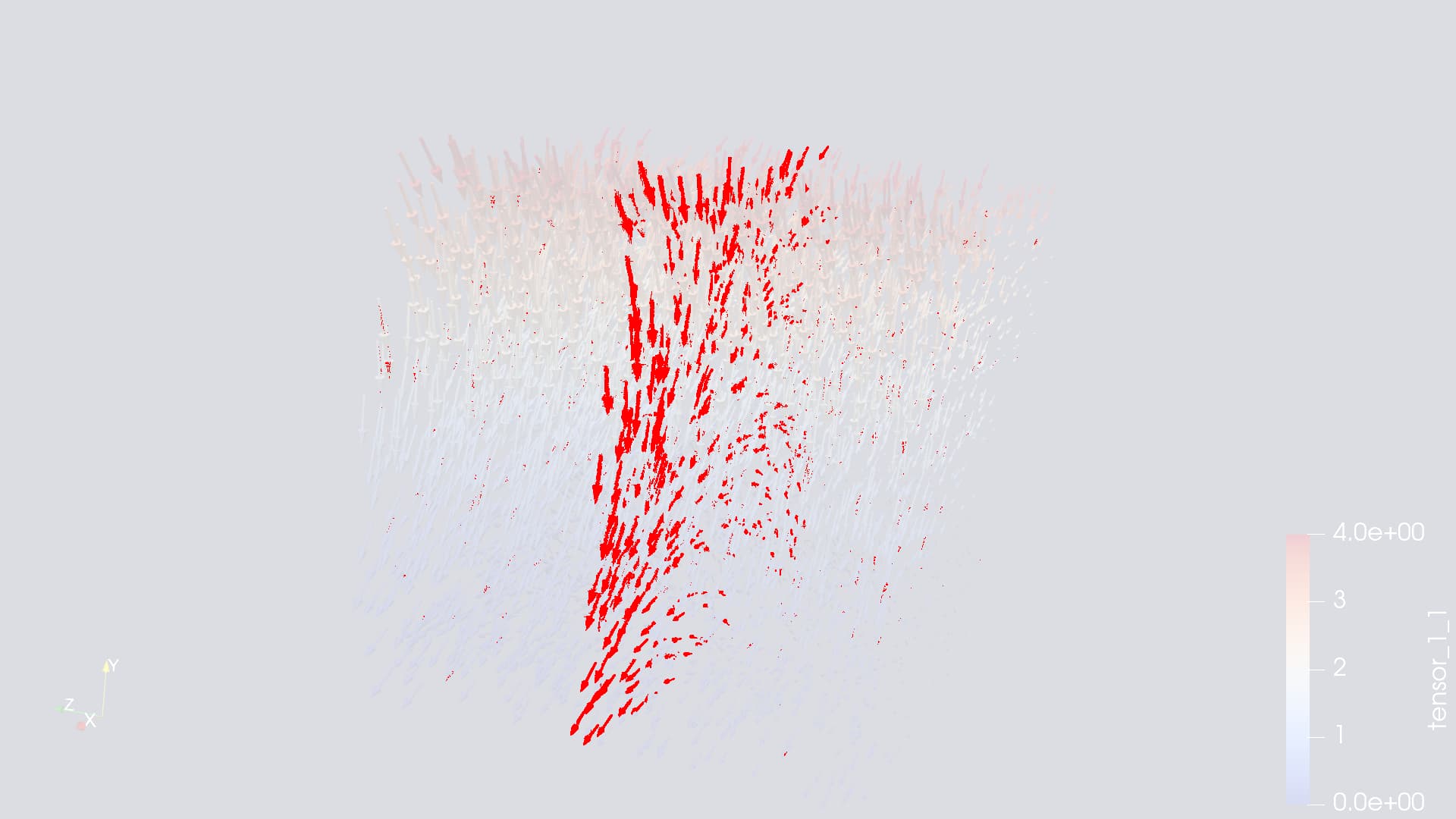
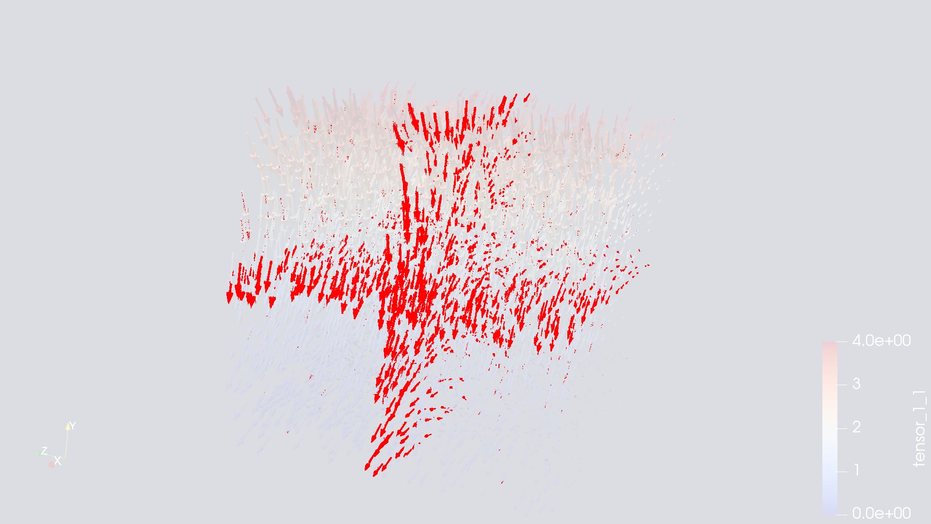
I am trying to visualize a particle simulation with in-situ Catalyst2 support, and while it is correct on single core (produced image is consistent with what ParaView creates), in multi-core setting I am getting artifacts on processes boundaries:
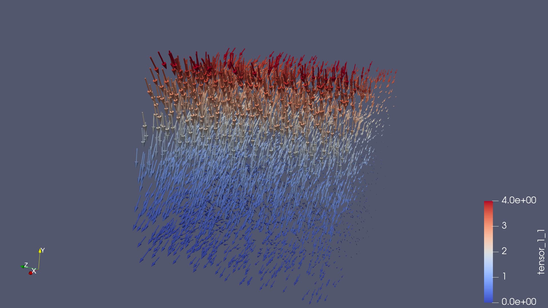
1-core Catalyst visualization:
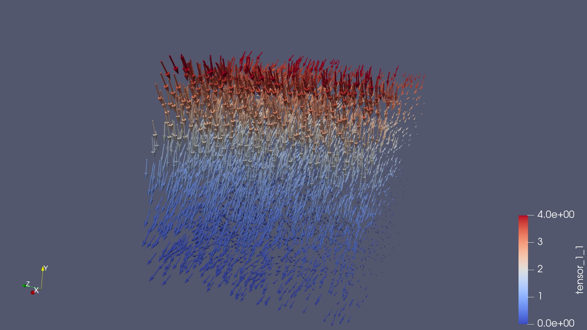
2-core Catalyst visualization:
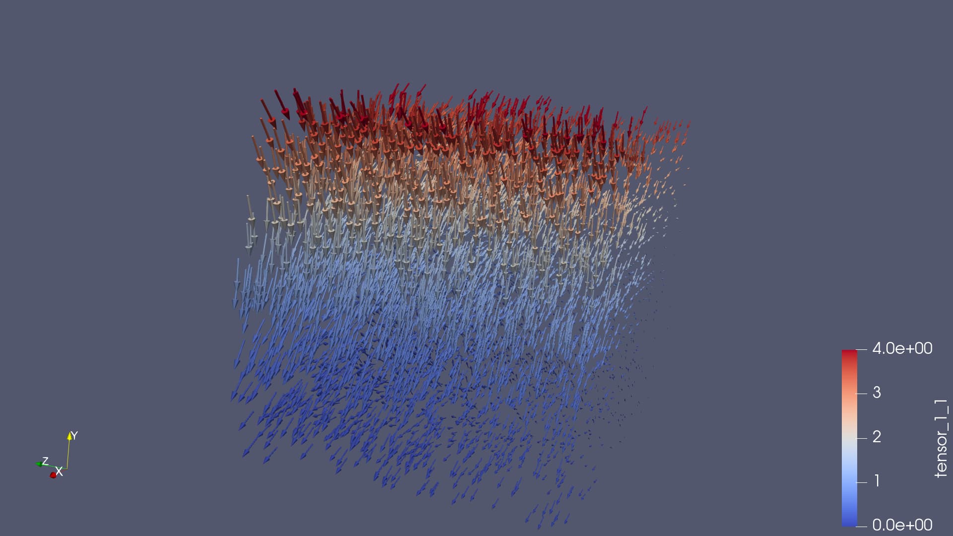
3-core Catalyst visualization:
2-core vs 1-core images difference:
4-core vs 1-core images difference:
Some details about simulation:
1. Data is list of particles, each particle has 3 properties - _scalar_, 3-dimensional _vector_, and 3x3 _tensor_ (unrolled into 9 separate scalar properties in the Conduit node field setter). In the images, glyphs are oriented w.r.t. _vector_, colored w.r.t _tensor[1][1]_, scaled w.r.t _scalar_.
2. Problem persists in the absence of ghost cells. I have verified that if 1-core gets 64K particles, then 2-core get 2x32K, 4-core get 4x16K.
3. I use the following Conduit Mesh Blueprint:
coords/type = explicit
mesh/type = unstructured
mesh/elements/shape = point
mesh/elements/connectivity = \
### Author:  [@utkarsh.ayachit](https://discourse.paraview.org/u/utkarsh.ayachit)
#### Post date: [December 12, 2023, 7:38pm UTC](https://discourse.paraview.org/t/catalyst2-artifacts-on-processes-boundaries/13489/2 "2023-12-12T19:38:15Z")
Are you showing glyphs for all points in the dataset ? Default is to pick a random set limited by a max count, IIRC. That can yield different set of glyphs as number of ranks changes, but will still be representing the data correctly.
---
### Author:  [@cartagena](https://discourse.paraview.org/u/cartagena)
#### Post date: [December 12, 2023, 8:49pm UTC](https://discourse.paraview.org/t/catalyst2-artifacts-on-processes-boundaries/13489/3 "2023-12-12T20:49:15Z")
Could you please elaborate on random set, how exactly is this tuned? What I did is the following:
1. Generate VTP for representative dataset with single core
2. Load VTP into ParaView, apply coloring and glyph filter, disable showing points, create PNG extractor
3. Save Catalyst state as Python script; change source to `TrivialProducer(registration_name="particles")`
So I guess I should be showing glyphs for all points
---
### Author:  [@Alexandre\_Minot](https://discourse.paraview.org/u/Alexandre_Minot)
#### Post date: [December 13, 2023, 7:26pm UTC](https://discourse.paraview.org/t/catalyst2-artifacts-on-processes-boundaries/13489/4 "2023-12-13T19:26:41Z")
Utkarsh is pointing out that in your step 2, when you add the Glyph filter, under “masking” in the property pane, make sure you use the glyph mode “all points” and not “uniform spatial distribution”.

---
### Author:  [@cartagena](https://discourse.paraview.org/u/cartagena)
#### Post date: [December 14, 2023, 1:44pm UTC](https://discourse.paraview.org/t/catalyst2-artifacts-on-processes-boundaries/13489/5 "2023-12-14T13:44:45Z")
Thanks, seems that random sampling was the problem, images are now consistent between single- and multi-core with “all points” mode. I guess there isn’t a mechanism to “synchronize” random sampling across processes in Catalyst (simulating working with .pvtp in ParaView)?