# Node positions of high-order Lagrange quadrilateral cells
**URL:** https://discourse.paraview.org/t/node-positions-of-high-order-lagrange-quadrilateral-cells/7012
**Category:** ParaView Support
**Tags:** high-order-elements, vtk
**Created:** [April 20, 2021, 7:34pm UTC](https://discourse.paraview.org/t/node-positions-of-high-order-lagrange-quadrilateral-cells/7012 "2021-04-20T19:34:28Z")
**Posts on this page:** 6
**Page:** 1
### Author:  [@sloede](https://discourse.paraview.org/u/sloede)
#### Post date: [April 20, 2021, 7:34pm UTC](https://discourse.paraview.org/t/node-positions-of-high-order-lagrange-quadrilateral-cells/7012/1 "2021-04-20T19:34:28Z")
Hi there!
We are trying to use the high-order Lagrange VTK cells first (?) presented in [this blog post](https://blog.kitware.com/modeling-arbitrary-order-lagrange-finite-elements-in-the-visualization-toolkit/). We’ve had some success in getting curved 4th-order `VTK_LAGRANGE_QUADRILATERAL` cells to be visualized in ParaView, but when comparing it on a rectilinear domain against the result of a classical, piece-wise constant `VTK_PIXEL` mesh, the results are somewhat underwhelming. We thus figure there might be something wrong with the way we create the Lagrange cells.
Just to recap, we create each `VTK_LAGRANGE_QUADRILATERAL` with 4 by 4 points, as shown in the blog:

However, the resulting images suffer from weird “spots” and a clear degradation of the quality near the element boundaries (here on a 2-by-2 mesh, each with a 4-by-4 Lagrange quad):
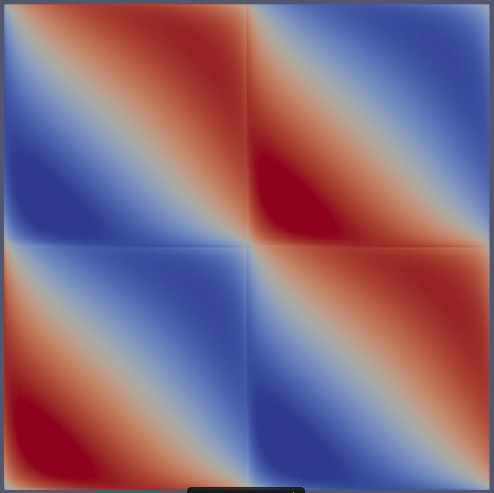
Is there anything that you need to be aware of when creating these cells besides the order of the points? For example, we are using the Legendre-Gauss-Lobatto nodes as the points for visualization - is this correct or would we have to use a different set of nodes (e.g., Chebyshev-Gauss-Lobatto, equidistant etc.)? Any kind of input would be highly appreciated!
---
### Author:  [@sloede](https://discourse.paraview.org/u/sloede)
#### Post date: [April 21, 2021, 12:50pm UTC](https://discourse.paraview.org/t/node-positions-of-high-order-lagrange-quadrilateral-cells/7012/2 "2021-04-21T12:50:03Z")
@ssss Since you seem to be quite experienced with the use of high-order cells (as evidenced [here](https://discourse.paraview.org/t/cell-data-vs-point-data-for-high-order-lagrange-cells/7015)), would you by any chance also know the answer to this thread?
---
### Author:  [@ssss](https://discourse.paraview.org/u/ssss)
#### Post date: [April 21, 2021, 1:34pm UTC](https://discourse.paraview.org/t/node-positions-of-high-order-lagrange-quadrilateral-cells/7012/3 "2021-04-21T13:34:28Z")
`vtkLangrange*` cells use equi-distant nodes (in the reference element). Therefore, it is (usually) necessary to interpolate solution data to such points. You may want to take a look at what we recently developed in PyFR to output high-order `vtkLagrange` cells using FR-DG simulations.
---
### Author:  [@sloede](https://discourse.paraview.org/u/sloede)
#### Post date: [April 21, 2021, 1:38pm UTC](https://discourse.paraview.org/t/node-positions-of-high-order-lagrange-quadrilateral-cells/7012/4 "2021-04-21T13:38:53Z")
> [@ssss](#):
>
> `vtkLangrange*` cells use equi-distant nodes (in the reference element).
Thanks a lot for the answer!
> [@ssss](#):
>
> You may want to take a look at what we recently developed in PyFR to output high-order `vtkLagrange` cells using FR-DG simulations.
That sounds like a great idea - are you referring to [PyFR/pyfr/writers/vtk.py at a63c25f858b483f443399ac55d2ec5dfbb273f8d · PyFR/PyFR · GitHub](https://github.com/PyFR/PyFR/blob/a63c25f858b483f443399ac55d2ec5dfbb273f8d/pyfr/writers/vtk.py)?
---
### Author:  [@erik-f](https://discourse.paraview.org/u/erik-f)
#### Post date: [April 22, 2021, 2:36pm UTC](https://discourse.paraview.org/t/node-positions-of-high-order-lagrange-quadrilateral-cells/7012/5 "2021-04-22T14:36:41Z")
@ssss How should the nodes look in a curved cell, then?
Once we allow non-Cartesian grids, we could define a mapping that maps the equidistant nodes in the reference element to any nodes in the physical domain.
Suppose we have one element, which maps onto `[-1,1]^2` in the physical domain. We run two simulations with different mappings. One with the identity mapping, one with a mapping that transforms the element such that we still get the same physical domain, but our nodes get mapped to different nodes (for example LGL nodes).
We evaluate our initial condition at the physical coordinates of our nodes, so we obviously get different nodal values in both simulations. However, both mappings of the interpolation polynomials should be identical in the physical domain.
---
### Author:  [@ssss](https://discourse.paraview.org/u/ssss)
#### Post date: [April 22, 2021, 2:52pm UTC](https://discourse.paraview.org/t/node-positions-of-high-order-lagrange-quadrilateral-cells/7012/6 "2021-04-22T14:52:35Z")
1. From VTK you get the parametric coordinates of the VTK reference element nodes.
2. In your code you interpolate your metric polynomials to the the parametric coordinates of the VTK reference node (beware, VTK uses [0, 1] as parametric coordinates I think) resulting in the physical coordinates of the VTK cell node.