# Visualization of Vector Field In Paraview
**URL:** https://discourse.paraview.org/t/visualization-of-vector-field-in-paraview/15431
**Category:** ParaView Support
**Created:** [September 24, 2024, 1:53pm UTC](https://discourse.paraview.org/t/visualization-of-vector-field-in-paraview/15431 "2024-09-24T13:53:28Z")
**Posts on this page:** 4
**Page:** 1
### Author:  [@Vamsi\_2001](https://discourse.paraview.org/u/Vamsi_2001)
#### Post date: [September 24, 2024, 1:53pm UTC](https://discourse.paraview.org/t/visualization-of-vector-field-in-paraview/15431/1 "2024-09-24T13:53:28Z")
while selecting the Glyphs filter for velocity contour the glyphys are going out of boundary for slice plane(Perpendicular),can we project the vectors on another plane,if so how to project them,see below attached images for reference purpose
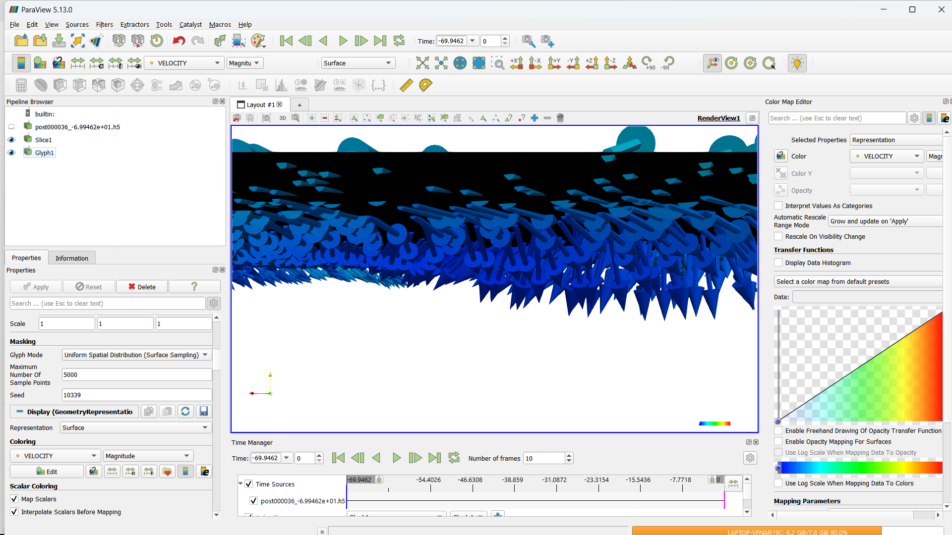
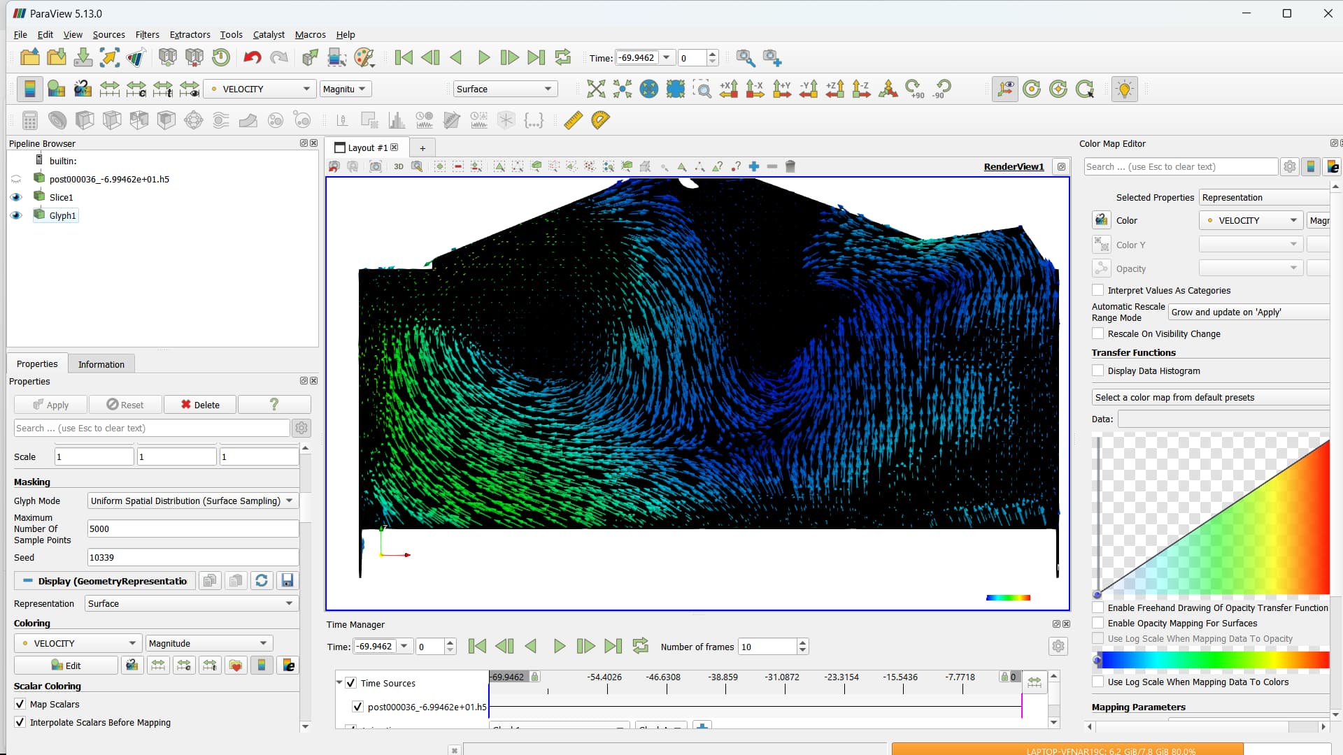
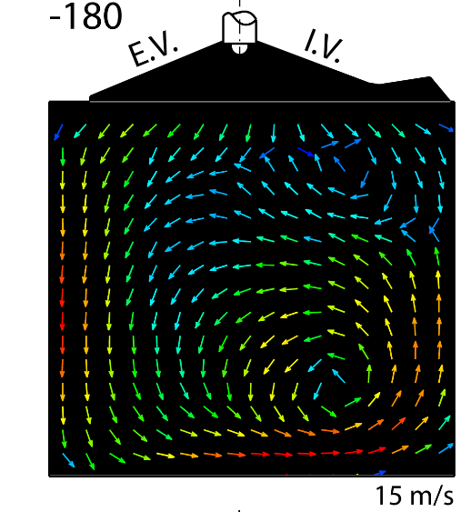
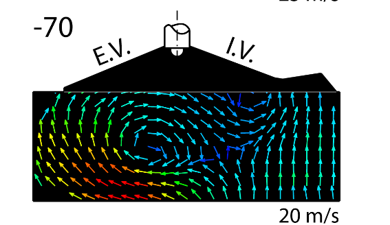
I want to create the velocity contour plot as shown below,please sort me out in this aspect
---
### Author:  [@mwestphal](https://discourse.paraview.org/u/mwestphal)
#### Post date: [September 24, 2024, 1:57pm UTC](https://discourse.paraview.org/t/visualization-of-vector-field-in-paraview/15431/2 "2024-09-24T13:57:09Z")
Hi @Vamsi_2001
Looks like your plane is axis aligned, so simply add a calculator on the slice and remove the Y component of the vector, eg:
`VELOCITY_x*iHat + VELOCITY_z*kHat`
then add your glyph filter.
---
### Author:  [@Vamsi\_2001](https://discourse.paraview.org/u/Vamsi_2001)
#### Post date: [September 24, 2024, 2:19pm UTC](https://discourse.paraview.org/t/visualization-of-vector-field-in-paraview/15431/3 "2024-09-24T14:19:38Z")
Thank for the quick response of my question, my Y axis velocity component issue is gone, but the glyphs are not uniform even after using surface based uniform glyphs as shown below
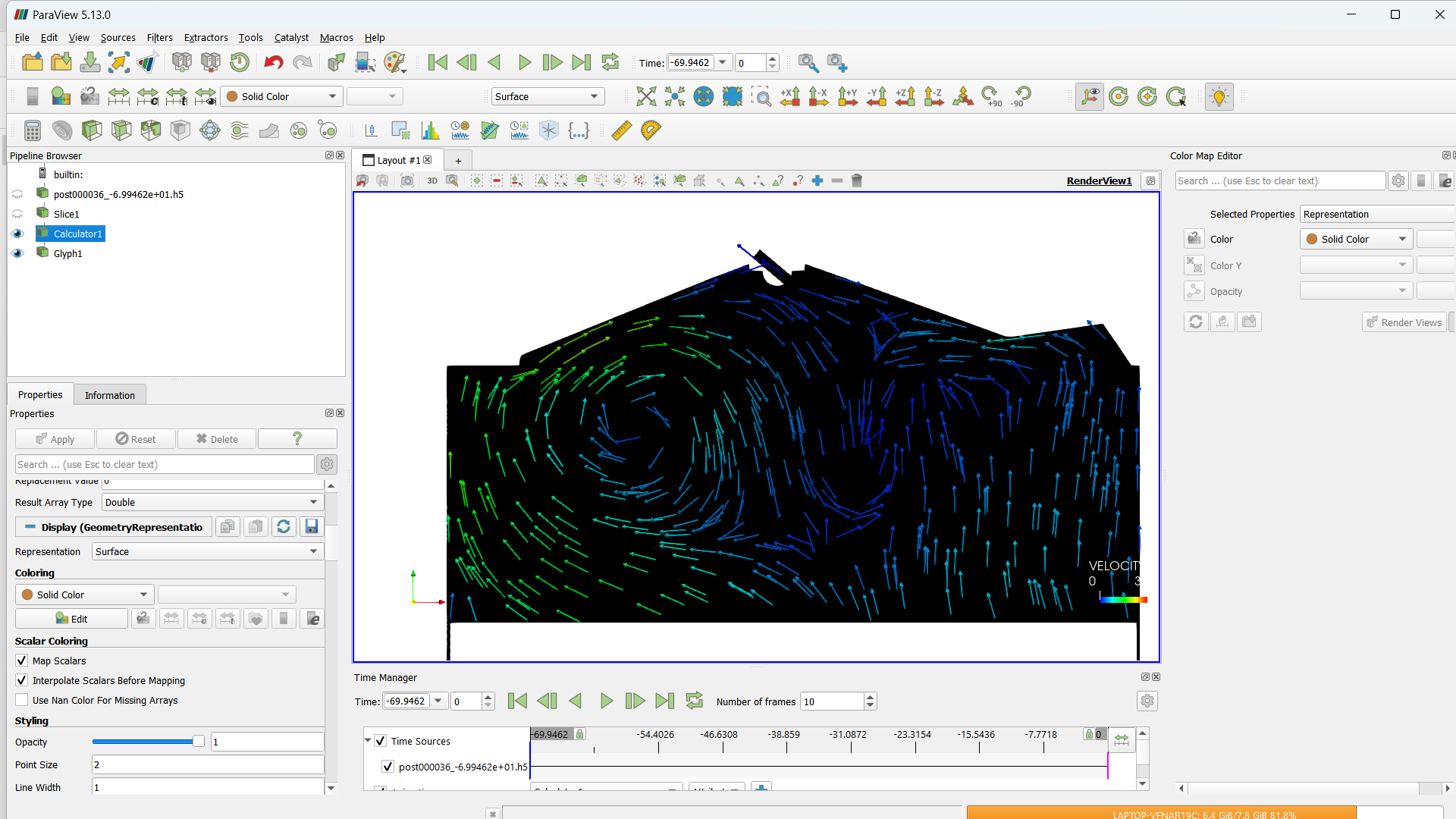
The target velocity contour for same profile is
---
### Author:  [@mwestphal](https://discourse.paraview.org/u/mwestphal)
#### Post date: [September 24, 2024, 2:26pm UTC](https://discourse.paraview.org/t/visualization-of-vector-field-in-paraview/15431/4 "2024-09-24T14:26:08Z")
You can try using Glyph Mode “Surface Sampling” to have a better repartitions of glyph, but keep in mind they are randomly positioned.
If that is not what you want, you will need to use evenly spaced streamlines first.