Viewing measurements in submicrometer

Hello,

I just started learning Paraview and sorry in advance if the problem I need help addressing is very trivial or have been answered before. :sweat_smile:

Currently I am using Paraview for postprocessing for a FEM simulation done on FreeCAD. The project that I am doing involves measuring dimensional changes in a submicron level.

airy1-CCX_Results.vtk (305.6 KB)

According to the color preset on the results obtained, there is a small change of 4.8 micrometer in the X direction. I am currently measuring the length change in the X direction from the midpoint to the end using the ruler function and the length always seems to round off to 50mm, instead of possibly 50.0048mm. Changing the scale under the label properties of ruler doesnt seem to work either. The dimensions of the block is 100 x 9 x 35 mm. I was wondering if there is any other tools on Paraview or a better way to use the Ruler tool to measure changes in the submicron level.

Thank you.

Client Information:
Version: 5.10.1
VTK Version: 9.0.20210922
Qt Version: 5.15.2
vtkIdType size: 64bits
Embedded Python: On
Python Library Path: C:\Program Files\ParaView 5.10.1-Windows-Python3.9-msvc2017-AMD64\bin\lib
Python Library Version: 3.9.5 (tags/v3.9.5:0a7dcbd, May 3 2021, 17:27:52) [MSC v.1928 64 bit (AMD64)]
Python Numpy Support: On
Python Numpy Path: C:\Program Files\ParaView 5.10.1-Windows-Python3.9-msvc2017-AMD64\bin\Lib\site-packages\numpy
Python Numpy Version: 1.21.1
Python Matplotlib Support: On
Python Matplotlib Path: C:\Program Files\ParaView 5.10.1-Windows-Python3.9-msvc2017-AMD64\bin\Lib\site-packages\matplotlib
Python Matplotlib Version: 3.2.1
Python Testing: Off
MPI Enabled: Off
ParaView Build ID: superbuild 6dd132601dbb2a9ebdc0d31825989f5b92595b76 (!969)
Disable Registry: Off
Test Directory:
Data Directory:
SMP Backend: TBB
SMP Max Number of Threads: 8
OpenGL Vendor: ATI Technologies Inc.
OpenGL Version: 3.2.14830 Core Profile Forward-Compatible Context 21.10.20.04 27.20.21020.4003
OpenGL Renderer: AMD Radeon™ Graphics

Connection Information:
Remote Connection: No

Hi,

First, the geometry must be deformed based on the displacement vector (Displacment) using the Warp By Vector filter. Then could you try Ruler?

1 Like

Yes! It works! Thank you so much, I did not know I had to do that (Warp by Vector).

May I ask if there is a instructional manual for the label format? The labelling of %4.10f helped me greatly in presenting my data. Are there other label formats that I can look into?

Thank you so much! Lifesaver :smiley:

Hi,

The format of the label is the same as the format in the C language. So would you refer to the C language textbook?

1 Like

Alright, I’ll look into the C language format.

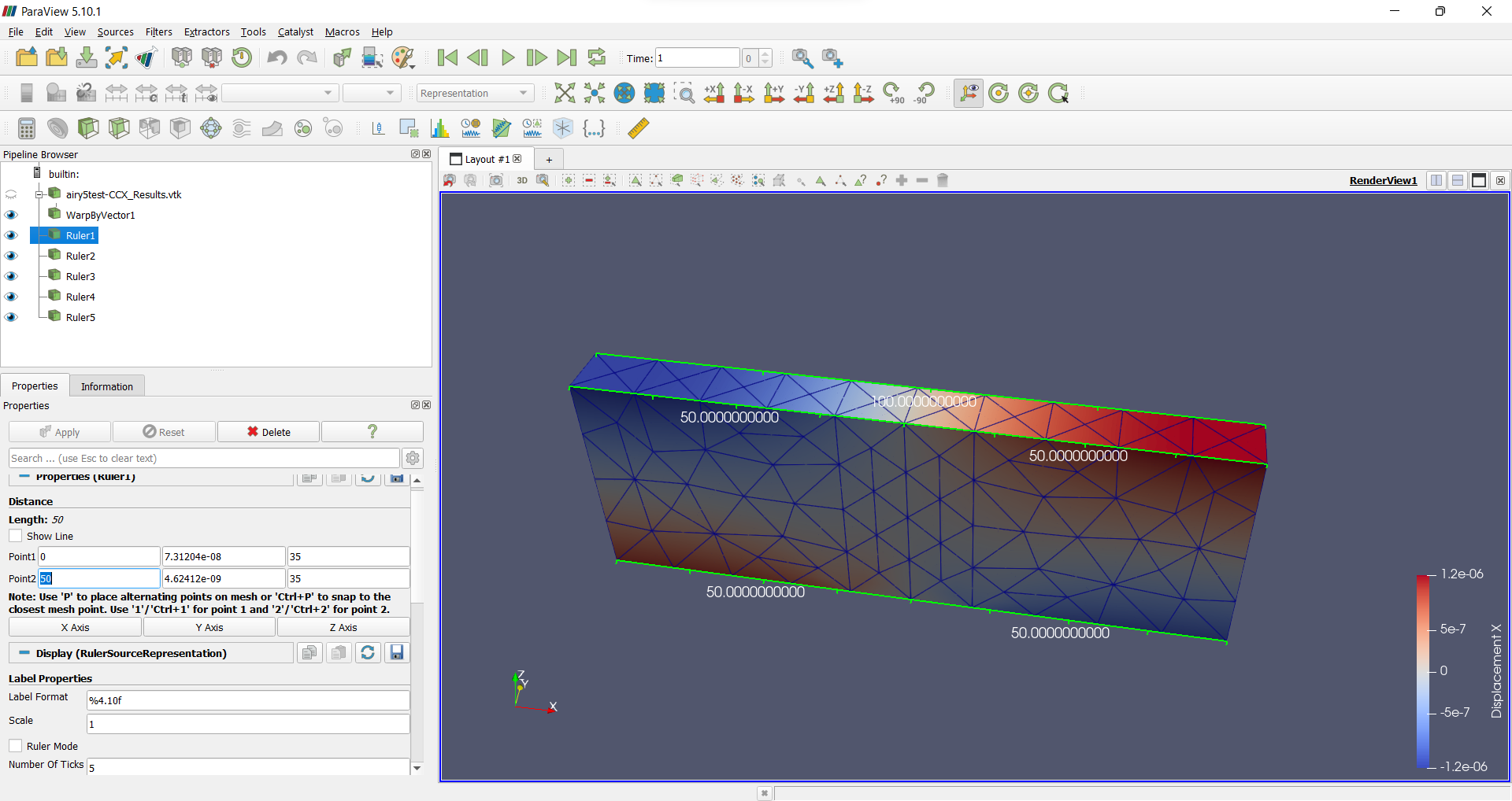
Sorry to trouble you again, I cannot seem to obtain an x-coordinate that corresponds to the change in displacement. From the legend or color bar, I am supposed to find the 1.2e-06 change in the X displacement. But measuring from one edge to another edge or midpoint, it still comes off as 50 and/or 0,50,100 in exact values.

Please advise, thank you. :sweat_smile:

airy5-CCX_Results.vtk (357.2 KB)

Even if I change line 5 in airy5-CCX_Results.vtk from float to double:

POINTS 1107 float → POINTS 1107 double

the Warp By Vector filter is still calculating single precision, so this seems to be a bug.

I have reported this below.
https://gitlab.kitware.com/paraview/paraview/-/issues/21439

1 Like