Adding thickness to a surface mesh

I have a spherical surface with a scalar field on it, as shown here in 3d and in a cross section:

I would like to give the surface a thickness, so that it looks more like this (surface has thickness and there should be no artifacts in the cross section):
target

What has not worked so far is:

  1. Change line width: Under Styling > Line Width. This has no effect on the 3d view. It only changes the width of the line in the cross section. However, the larger line thickness leads to tiny evenly spaced dark artifacts.
  2. Extrusion: After applying Extract Surface, the Linear Extrusion filter can move the mesh surface in a direction, but it is constant for each element of the mesh. Is it possible to set the extrusion direction as the surface normal?

Is there another way/filter available to achieve this?

I attach the geometry and the paraview state file:
sphere_surface.vtu (706.5 KB)
surface_thickness_issue.pvsm (699.2 KB)

2 Likes

I’m afraid there isn’t, but a NormalExtrusion filter would make sense in ParaView.

You should be able to implement in a python ProgrammableFilter though.

Hello,

A simple work around is to use the Delaunay 3D filter if adding thickness to a sphere. See the attached state file:
delaunay_3d.zip (393.0 KB)


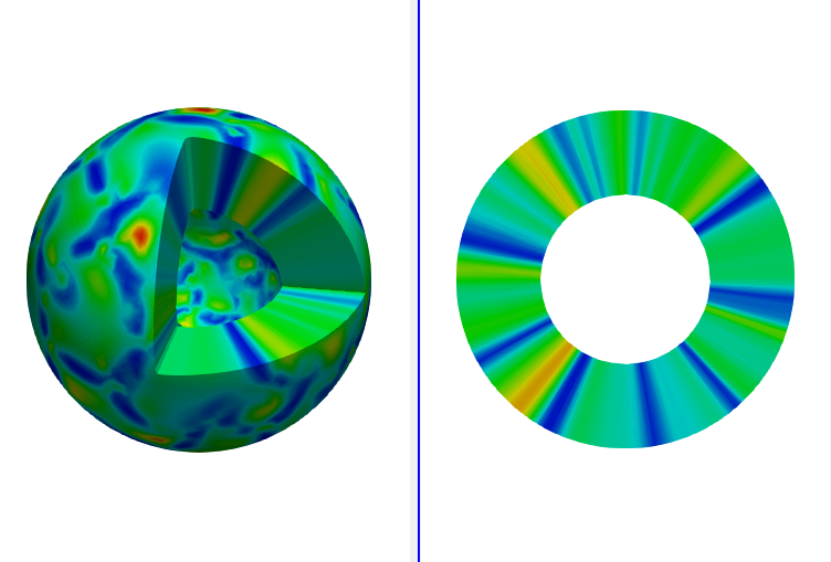
But, the cutting surface by the Clip filter with box might not be very sharp as shown in the upper left figure.

1 Like

Very neat. To make the sphere hollow, the trick is to clip a sphere out of it, correct? Is it possible to clip non-standard volumes as well, so one could use the approach for a non-spherical shape?

Hello,

For a non-spherical shape, it is needed to use the Programmable filter so that the surface of the shape is extruded in each surface normal direction. As the simplest example, the state file is attached:
extrusion.zip (356.1 KB)

And, the figure below shows the result.
extrusion

Here is programmable filter:

  • Output Data set Type: vtkUnstructuredGrid
  • Script:
import numpy as np

pdi = self.GetInput()
ugo = self.GetOutput()
ugo.Allocate()

scale = 0.2

num_pts = pdi.GetNumberOfPoints()
num_cells = pdi.GetNumberOfCells()
new_pts = pdi.GetPoints()
in_pd = pdi.GetPointData()
out_pd = ugo.GetPointData()
out_pd.CopyAllocate(in_pd);

normals =in_pd.GetArray('Normals')

id_map = {}
for i in range(num_pts):
    point = np.array(pdi.GetPoint(i))
    normal = np.array(normals.GetTuple3(i))

    j = new_pts.InsertNextPoint(point+normal*scale)
    out_pd.CopyData(in_pd, i, i)
    out_pd.CopyData(in_pd, i, j)
    id_map[i] = j

ids = vtk.vtkIdList()
for c_id in range(num_cells):
    pdi.GetCellPoints(c_id, ids)
    new_ids = ids
    for id in range(ids.GetNumberOfIds()):
        extruded_pt_id = id_map[ids.GetId(id)]
        new_ids.InsertNextId(extruded_pt_id)

    ugo.InsertNextCell(vtk.VTK_WEDGE, new_ids)

ugo.SetPoints(new_pts)
2 Likes

Nice work @Kenichiro-Yoshimi !

If you feel like it and can write C++, this would be great in VTK.

This is awesome! Let me point out that this also generates good data for the sliced view. The slice edges can be made more accurate by running a loop subdivision beforehand on the surface.

One issue is that the filter changes the array of normals.

original_normalsmodified_normals

This has two downsides:

  1. The parameter “scale” can not be changed after its application (produces an error).
  2. The surface rendering looks bad when extruding the surface to the outside (scale=-0.2, since the normals point inwards in the mesh).

What seems to resolve the issue is replacing the line

new_pts = pdi.GetPoints()

with

in_pts = pdi.GetPoints()
new_pts = vtk.vtkPoints()
new_pts.DeepCopy(in_pts)

There might be a better way to do this though.

There is still a problem with the lighting unfortunately due to the new normals.
new_normals bad_lighting

Is there a way to separate the old from the new normals (so one can flip only the old ones later, since they are now pointing inside the volume)?

Attached is the state file for the image illustrating the lighting problem:
spherical_extrusion_v2.pvsm (632.3 KB)

1 Like

Thank you for trying and making several improvements!

The simplest way to avoid the lighting issue might be to remove the array of normals in the Programmable filter script.

out_pd.RemoveArray('Normals')

Here is the state file spherical_extrusion_v2_1.pvsm (643.8 KB)

1 Like

Yes, that works to kick out the incorrect surface normals.

After the programmable filter, one can then use this to get the correct normal vectors:

  • Clip
  • Extract Surface
  • GenerateSurfaceNormal

This will also generate normal vectors on the cut surface leading to subtly improved lighting:

1 Like

Awsome figure!

I notice that the simulated value is the same along the vector, i.e. pointing to the centre of the ball. What
s the perspective can this figure offer to readers?

I am simulating a thin shell which can be approximated by its midsurface. The figure is very helpful in showing the actual geometry of the physical problem.

1 Like

Hello,

I tried reproducing this solution for something I am working on and it doesn’t quite work.

Here’s my pipeline: state.pvd > ExtractSurface > Threshold (integer) > ProgrammableFilter (one proposed here).

Naturally, the programmable filter wasn’t going to work in this situation because there are no normals to operate upon. When I insert the programmable filter one level above, it seems to work (bit tricky to tell right now). However, I only want a subset of the surfaces that are embedded inside a domain to be offset with some thickness.

I tried clipping the domain of interest and then extracting surfaces but that doesn’t seem to work.

Thanks!

Vikas