I’m trying to render view my 3D mesh with color from one of the data value (solution_re, in the pictures below). While the color legend appears to be alright, the mesh’s color is quite not right. Any help about what I am missing here ? I’ve included a few screenshots of the problem here.
My paraview is 5.11.1 on Mac OS (Ventura). My vtu file size is too large to be uploaded here (28 MB) but is available as a zip file here: Vtu file…
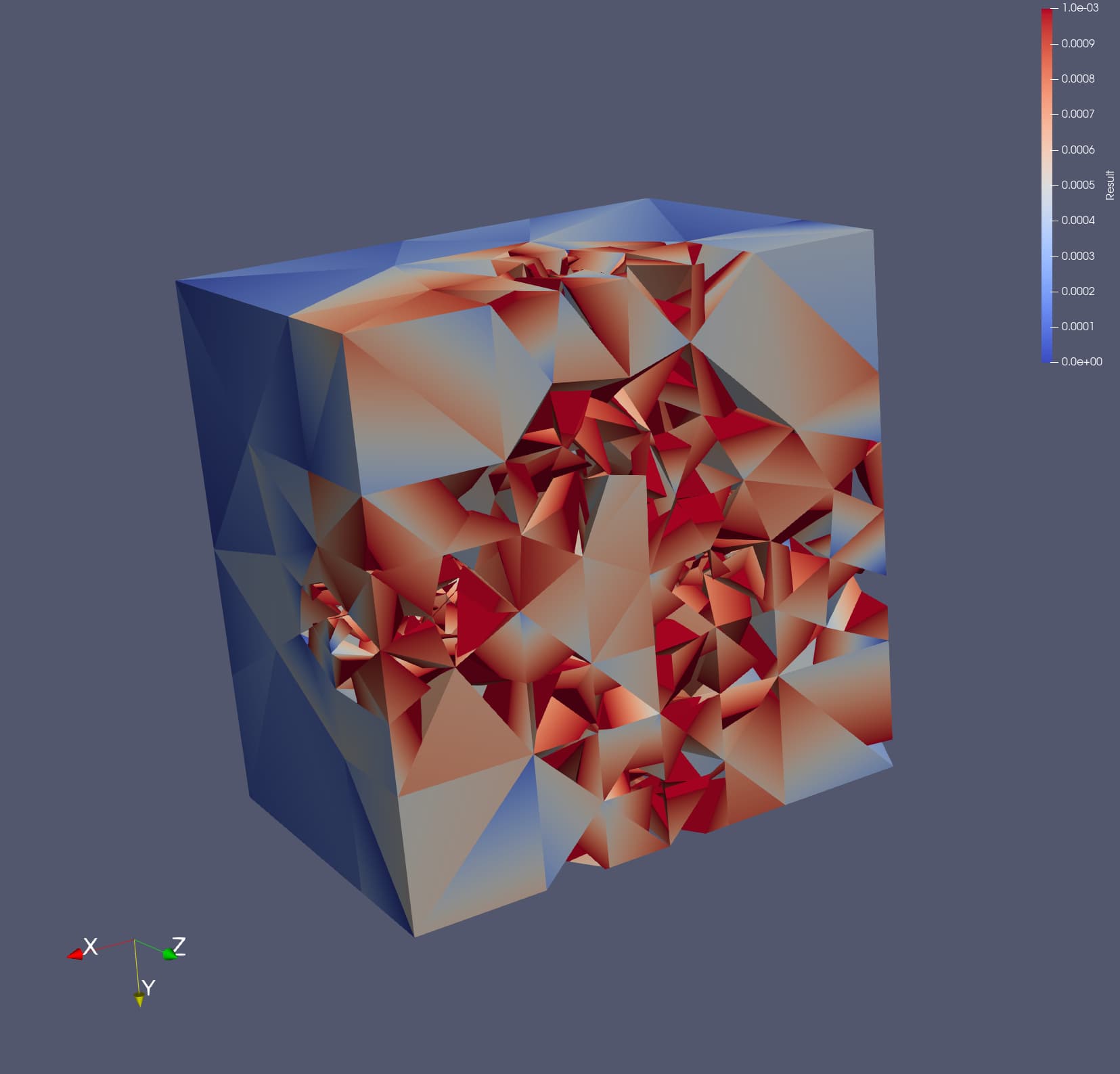
I see ! Now I can reproduce the image you posted (the clip direction does not matter much) ! So the problem was the data scale is too close to small values. I think it makes sense since my data field is supposed to decay exponentially over the mesh.
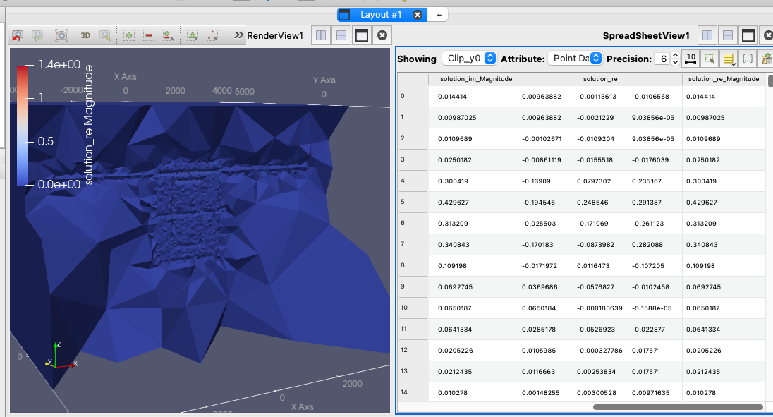
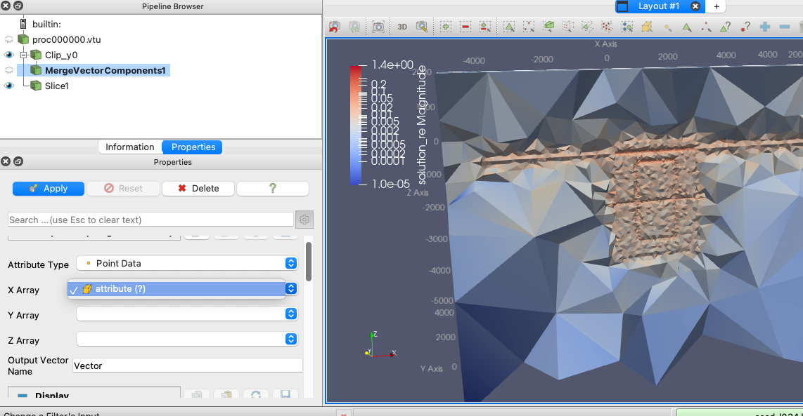
Do you know how to plot 3D Glygh or vectors using my data ? If you use the spreadsheet view to check the data, you can see that there’s 3 components for “solution_re”, but I can’t figure out how I can choose those three columns of data in filter Merge Vector Components. In my case, there’s no available components to choose when using this filter (see the screenshot below)
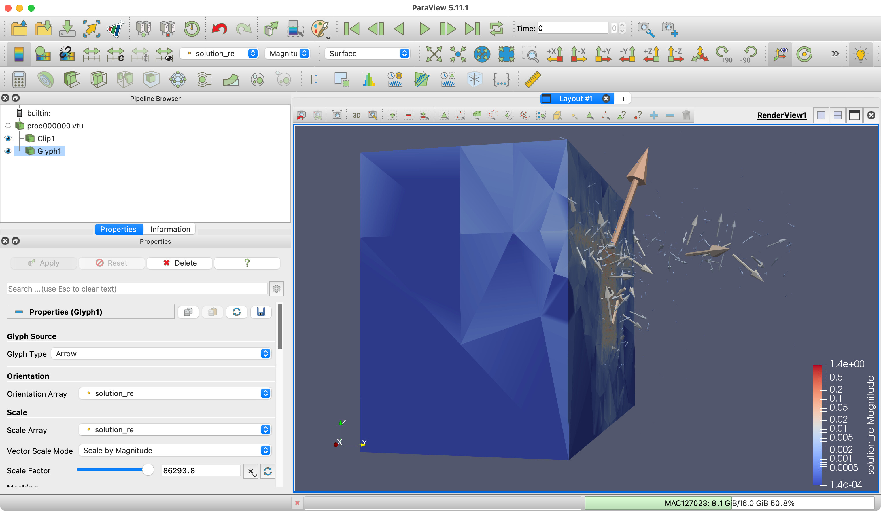
Why do you think you need to run the Merge Vector Components filter? The components of the vector are already merged in a single vector. Just run the Glyph filter and orient by solution_re. (If you scale by solution_re, you will probably need to bump up the Scale Factor because of the aforementioned unbalanced range of sizes.)
The components of the vector are already merged in a single vector.
Could you explain more here about this ? Actually, when I select the Orientation Array as solution_re, I don’t know exactly what is going on here. Does Paraview do some interpolation here ? Another complication is, I don’t quite understand the amount (270,744 for the total mesh) of data points shown here in Paraview. Since my mesh has only 11451 vertices, I believe these point data are interpolated data points, somehow.
The original solution_re array contains one vector (i.e., 3 scalar values) on each edge of the mesh (total edge number is 79297). When saved over the mesh in another code, I think something happened there. Maybe these data points shown in Paraview were generated in that saving process.
I don’t know what else to explain. Your vectors are registered as vectors. They are the things that would be created by Merge Vector Components if the components were in separate fields. When you select the vector field as the orientation array, the glyphs are oriented by the vectors. That is, the glyph arrows will point in the direction of the vectors.
No. Glyphs are drawn at the locations of the points.
Now that you point that out, that’s weird, but ParaView isn’t doing that. There are 270,744 points in the .vtu file you posted. You can see that by looking at the text part of the file:
Something must have happened before you saved the file to add all those extra points. I believe that the cells are not properly sharing points. I note that you have 67,686 cells, each cell is a tetrahedron (4 points), and the number of points is 67686 \times 4 = 270744. So, whatever is creating your mesh is writing separate points for all tetrahedra.
You can correct that in ParaView using the Clean to Grid filter. That said, this probably won’t make much difference when running the Glyph filter for reasons I won’t get in to.