Here are a couple prototype images we’ve developed, along with a description of how we generated them and what follow-on work would be needed to “productize” them. In either case, there would also be follow-on user-interface work to make ParaView recognize fiber orientation data and allow users to select a layer to view (perhaps on a per-block basis). Also, neither of the prototypes focused on rendering multiple layers at once by extruding the shell to produce a more physically accurate geometry; based on the discussions we’ve had, that did not seem as much of a priority.
Approach 1: SLIC (Surface Line-Integral Convolution)
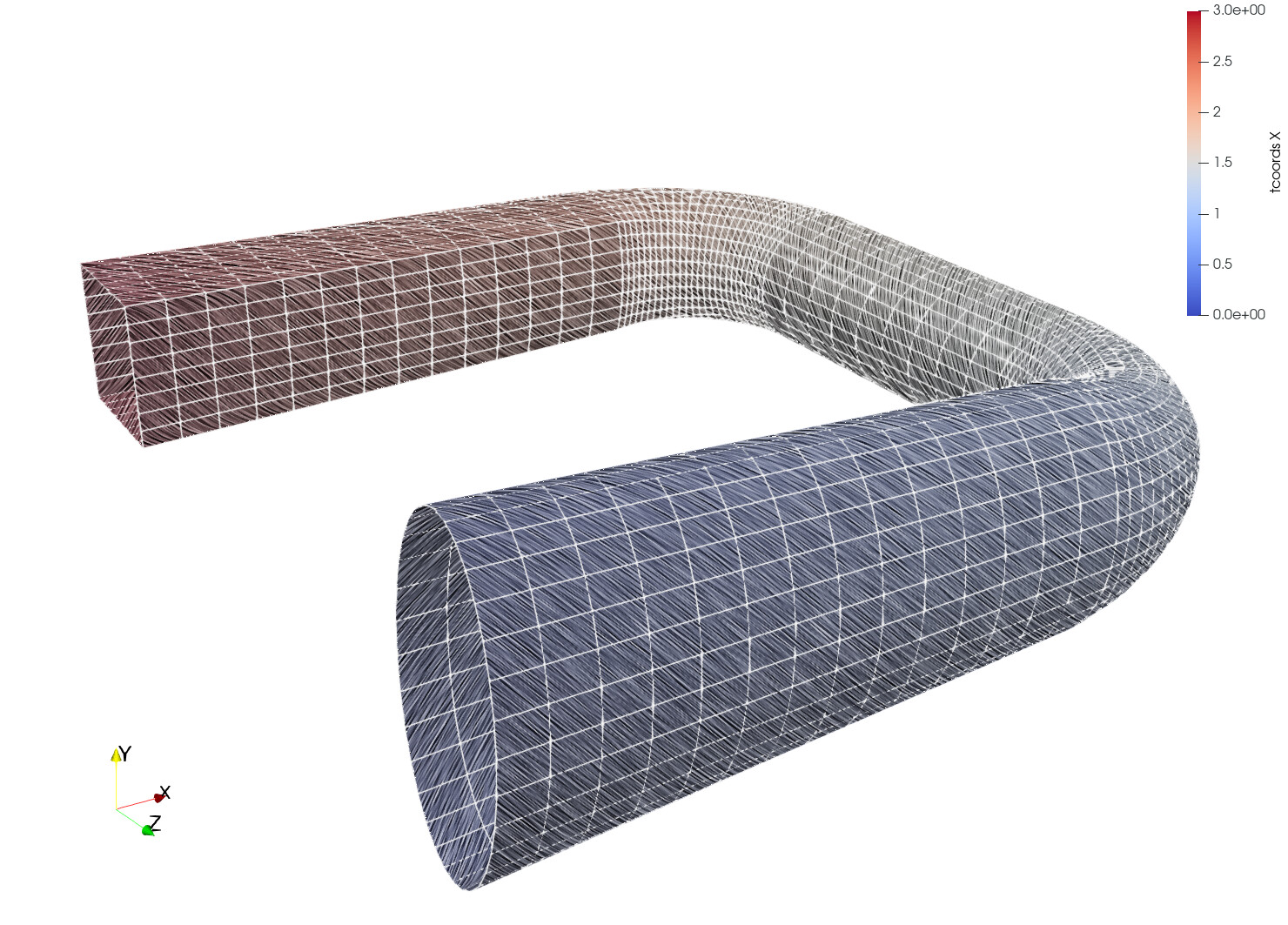
We used the “SLIC” representation in ParaView to smear Perlin noise along the surface of the sample part anisotropically. The surface color (the usual cool-to-warm colormap) might encode a stress magnitude. This color is modulated (made darker or lighter) by the smeared Perlin noise. Because the smearing occurs principally along the direction of the fibers, it conveys the fiber orientation. The pictures below show the same part but with “fibers” oriented differently: in the first, the fibers are parallel to the longitudinal axis of the tube while in the second the fibers are wrapped at 45 degrees to the longitudinal axis.

Benefits and Drawbacks
This approach generates nice images but the post-processing code does slow rendering down. It can also be tricky to get the right amount of lightness to see the coloring clearly while also leaving the fiber orientation apparent.
Follow-on Work
If we decide to use this rendering technique, we would need to investigate whether there are ways to improve the performance of rendering and automate the choice of parameters to balance fiber contrast and color perception.
Approach 2: Texturing
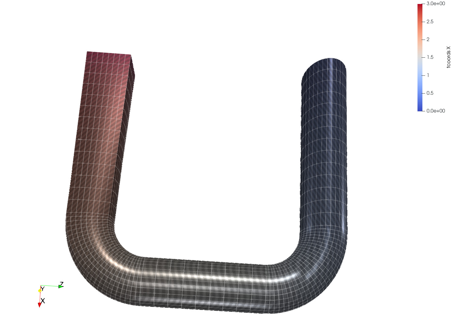
This uses ParaView’s PBR (physically-based rendering) extensions to apply textures that simulate carbon-fiber material. Multiple textures can be used (one that modulates the scalar colormap being applied to show stress, one that describes the roughness of the fiber surface, one that modulates the surface normals to produce complex specular highlights, etc.). As such, this allows a wide range of appearances as the two pictures below illustrate. They show the same fiber orientation but with different trade-offs between photo-realism (top) and scalar color visibility (bottom).

Benefits and Drawbacks
This approach is fast to render and produces high-quality images but again there are trade-offs to consider in terms of how easy it is to perceive the scalar being visualized with color compared to the textures used to illustrate fiber orientation. The other drawback is that this approach requires a texture atlas for the part.
Follow-on Work
Texture atlases are not something ParaView can generate at the moment, though some preliminary work has started to make this available. Also, support for transforming the texture (i.e., rotating and scaling the texture image on the surface being textured) was present in VTK but not exposed in ParaView. As part of prototyping, we added this feature to ParaView.
Conclusion
After evaluating the prototypes, we feel that the second, texture-based approach is the best path forward and hope to start implementing features to support this as funding becomes available.