I use a Velodyne VLP-16 LiDAR and an Advanced Navigation (Spatial) GNSS device. I have a *.pcap file with a position orientation reader with global x,y,z, and roll, pitch,yaw. I have generated a csv file with position with timestamp. Now is it possible to slam lidar data with an external sensor, currently I’m facing an issue with doing that.
Hi @Nitin_Garg,
Which version of LidarView are you using?
You should be able to load the csv file in the SLAM filter, in the property dock widget and the field External Sensor File.
Hope this helps,
Timothée
Thanks for your reply @Timothee_Couble. I am using version 4.5.0 and I have tried the slam filter and selected external sensor file. My csv file is attached below. The trajectory generated by the slam is different from the actual position orientation trajectory. I am giving epoch time in csv.
Please help me to solve this. I am a bit new to this.
Thanks.
RawSensorsnew.csv (1.0 KB)
@Timothee_Couble @Gatien_Ferret
Please help me to resolve this.
Hi @Nitin_Garg,
The external sensor is a measurement in the SLAM, but it is not the only one so the resulting trajectory may not be exactly the same. To make it follow it more closely, set a high value in the Pose Weight field.
Strange thing about your data is that you seem to have only one measurement per second ( each line is incremented by 1 in the time array) when such sensors usually output a much more frequent data.
Also, you need make sure you are providing it a calibration matrix ( to link the pose measurements you have to the LiDAR / SLAM coordinate system ), as explained in the external sensor guide.
For an easier interface, you may use latest LidarView build ( link from there → Download artifacts for your system).
You may subscribe to a contract support ( 10 hours should be sufficient) if you would like us to test directly on your data and debug the process on your data.
I hope this helps.
Hi @Gatien_Ferret,
Thank you for your helpful response.
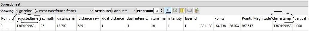
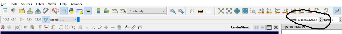
I have a question regarding which timestamp should be used to synchronize data with GPS/IMU timestamps. The GPS timestamp is in Unix (epoch) format, such as 1718857370.63. However, I’m uncertain which timestamp from the frame (pcap) data should be synchronized with this. The frame data includes timestamp, adjusted time, and frame time.
This question might seem a bit unconventional, but clarifying this will greatly assist me in my work. I have attached updated CSV files below for your reference.
RawSensors_final.csv (3.1 MB)
@Timothee_Couble
Hi @Nitin_Garg ,
By default the SLAM uses the points from the LiDAR (Time Synchronization parameter == LiDAR frame), and the most accurate approach is to compute the offset between those points and the raw sensor time so that it doesn’t rely on network time that may fluctuate. To do this, you would need to manually calculate the offset between the first point and the network time and modify your csv file accordingly.
Though, you may rely on the network time in the SLAM for this synchronisation.
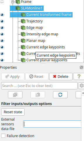
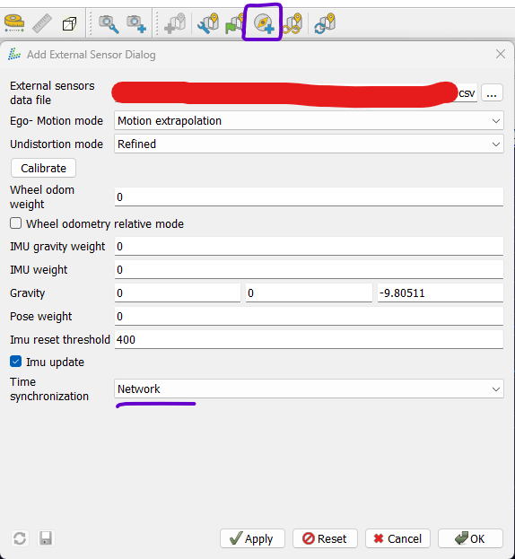
With the latest versions ( as shared above), you should have access to the SLAM toolbar that eases up the use of external sensors, once your SLAM is enabled you may add external sensor data with the highlighted button and select the Network synch mode as shown below.
For a more complete use of the toolbar for external sensor usage, you may also look at this video
I hope this helps.
Gatien
Thank you for your response.
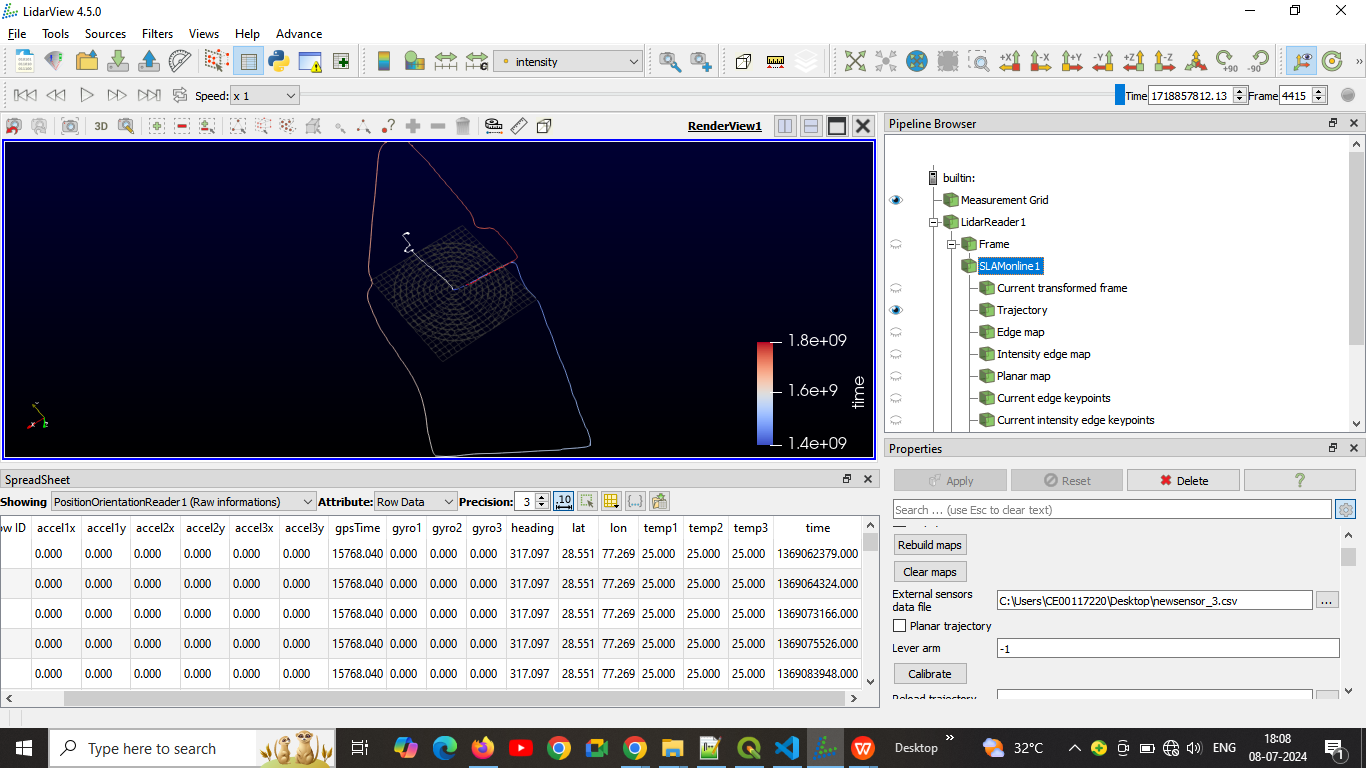
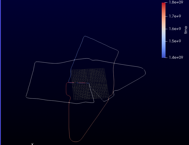
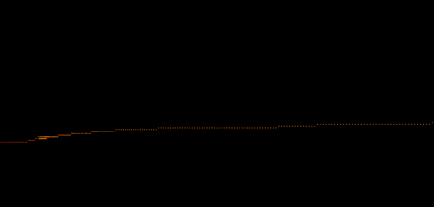
In my case, the PCAP file includes pose orientation data. When I enable the pose trajectory, it is displayed clearly. However, after running the SLAM process, the resulting trajectory differs.
Please refer to the snapshot below. The red and green trajectories represent the pose trajectory, while the white one represents the trajectory created after the SLAM process.
Hi Nitin,
The SLAM trajectory is in the LiDAR coordinate system, the Pose is in the GNSS coordinate system, so by default there is no reason for them to be aligned.
Though, you may modify the initial pose of the SLAM if you would like to align it with the GNSS.
Note: in your case, as you come back to the initial position, you may also want to use a loop closure constraint. See more details on this here and here
Hello Gatien,
When I used poses and position of first point from IMU and GNSS to initialize the SLAM, it worked but the output looks messed up for some reason. There is some pattern.
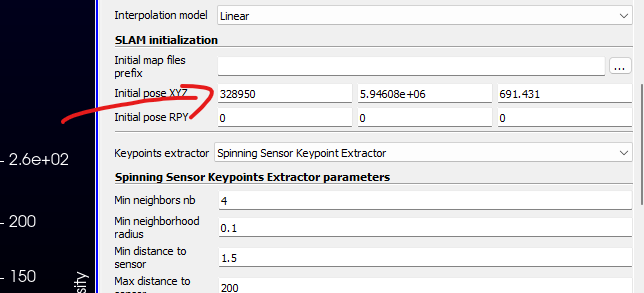
Output looks like this:
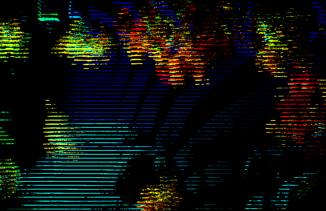
It has to do with the large coordinates or something but I am not sure if there is a fix for it.
Another question, when I added RPY to the initial pose, it produces bad output, is there a reason for that! I tried Yaw only and it improved a bit but it was still off.
Much appreciated.
That seems to be an issue due to an optimization of the visualization in VTK for large coordinates. I haven’t found any open issue describing, nor have I characterized it well enough to create a relevant one.
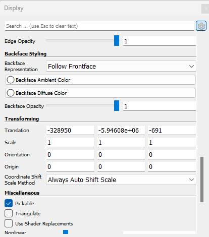
It shall be improved if you apply an inverse transform in the display properties to send back the data close to 0 for the visualization. But this is not an ideal solution ( I still see some artifacts when doing so).
But this is clearly a point of improvement important to LidarView, whether it is improved through a VTK update or if we find a workaround to deal with that in a better way in LidarView.
How would you apply an inverse transform within lidarview?
I got the same question, @Gatien_Ferret
Thx so much.
That would be through the Display properties ( which you may open from View → Display then press the cogwheel ) as below :