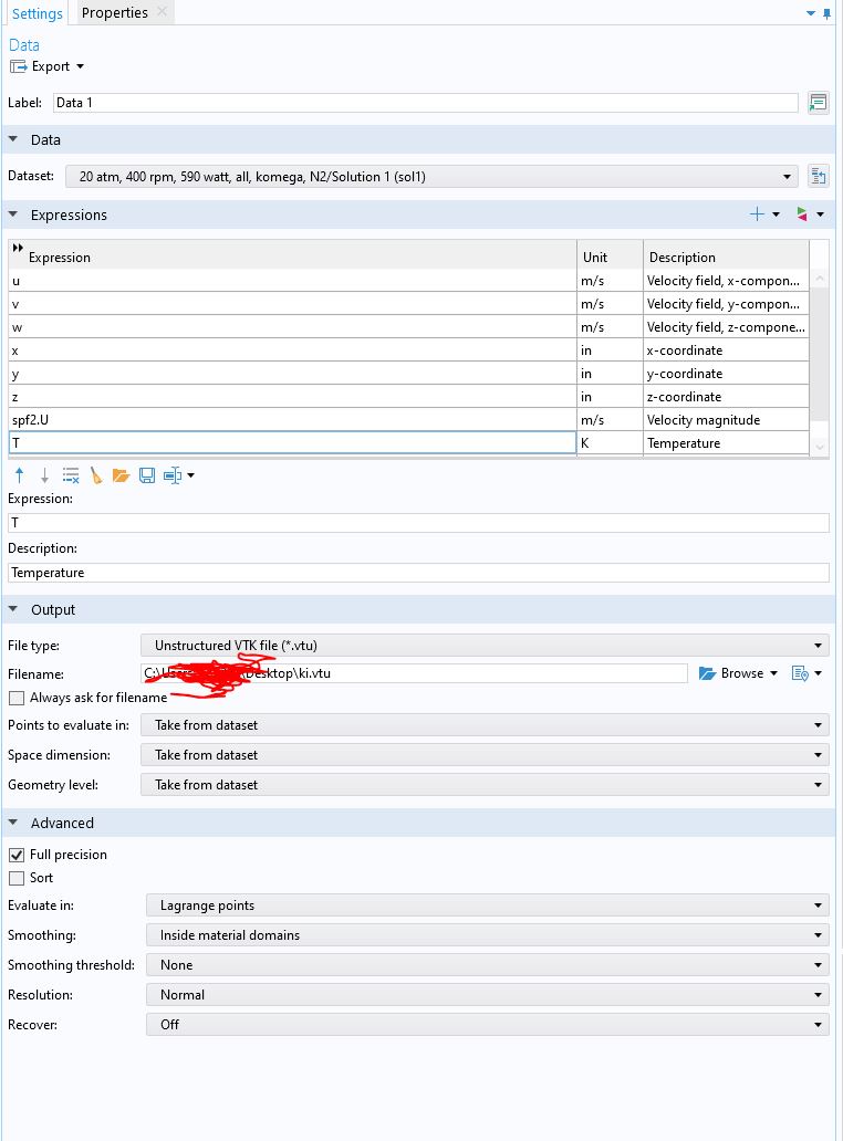
I want to see the streamlines in Paravie using COMSOL data. I export data as VTK (please see attached files). The streamlines look fine in my COMSOL sample file but I can not see the streamlines in Paraview after I load data in Paraview. The tracer filter is greyed out.
Velocity or temperature contours are working properly tho on a 2D plane.
I appreciate any tips.
I am afraid that it is not an option for now.
Are you aware of a specific data format that ParaView needs to process data?
Or any other tips that I could check on my end?
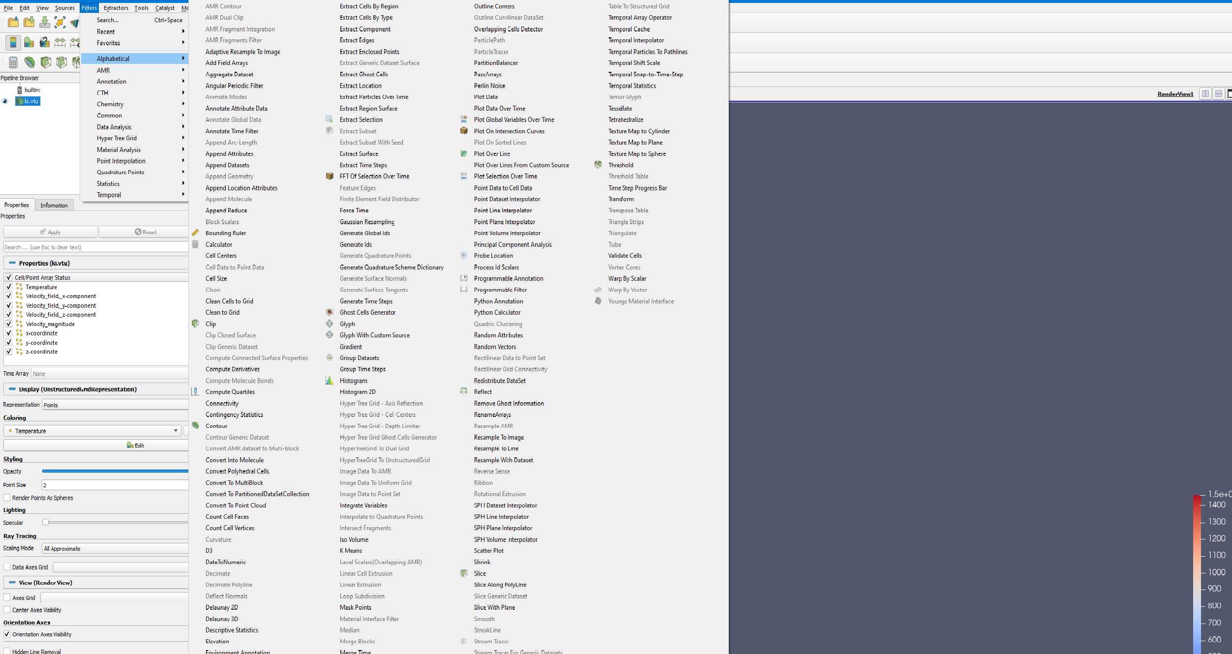
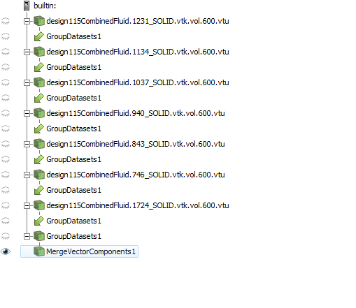
To utilize the Stream Tracer filter, it is necessary to construct a velocity vector. This can be accomplished by employing the Merge Vector Components filter to combine the three component variables of velocity present in the data.
Thank you for your response.
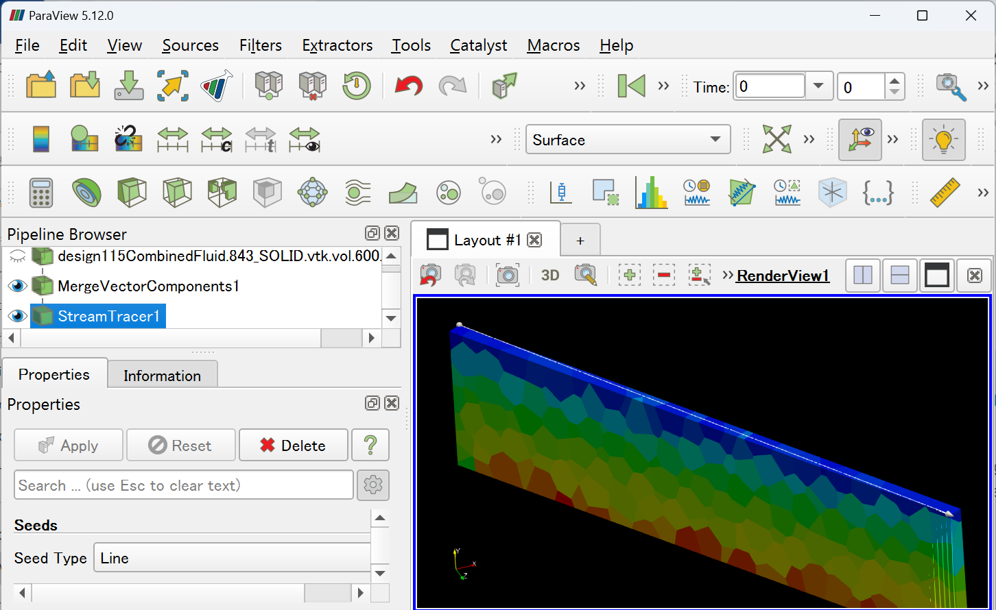
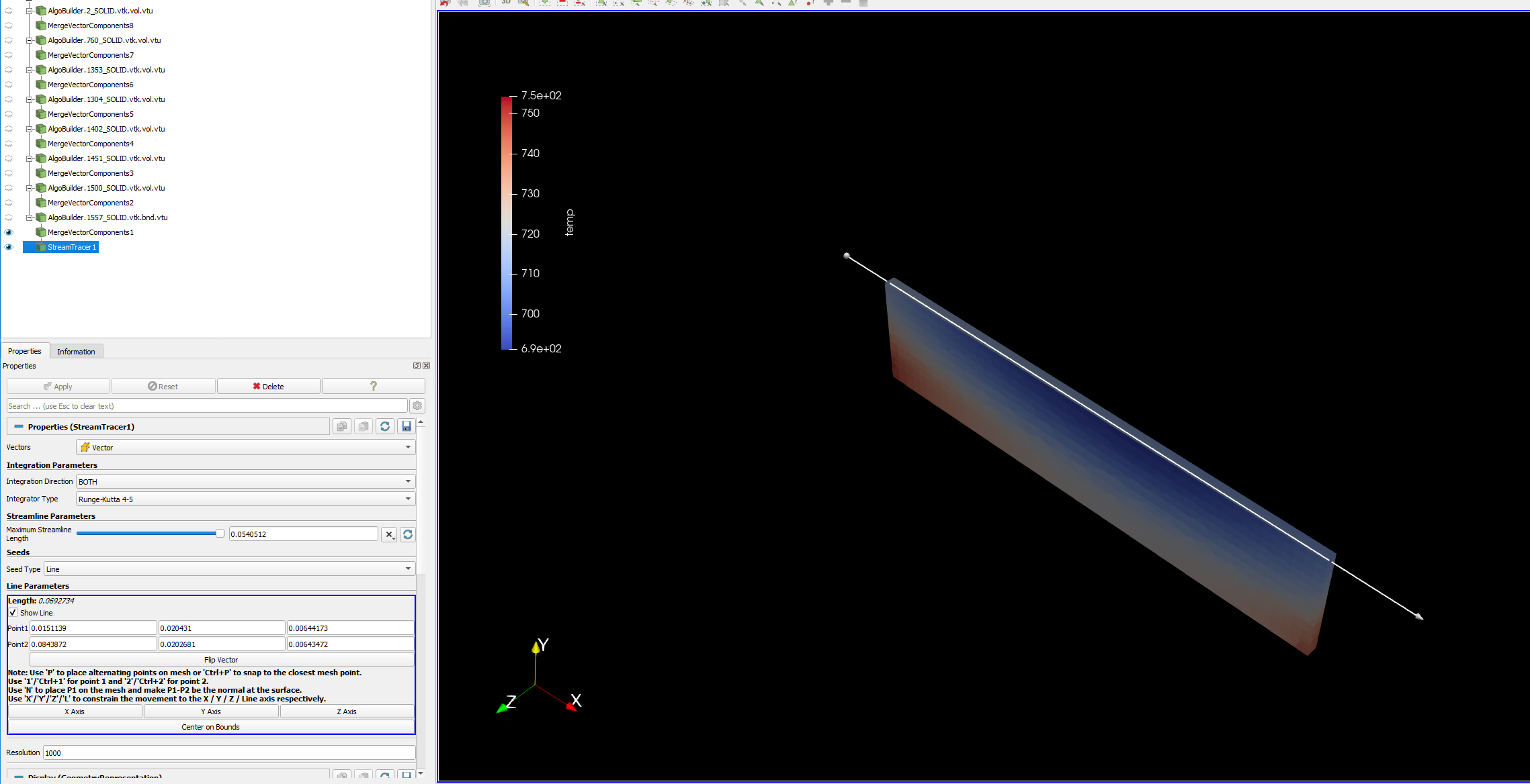
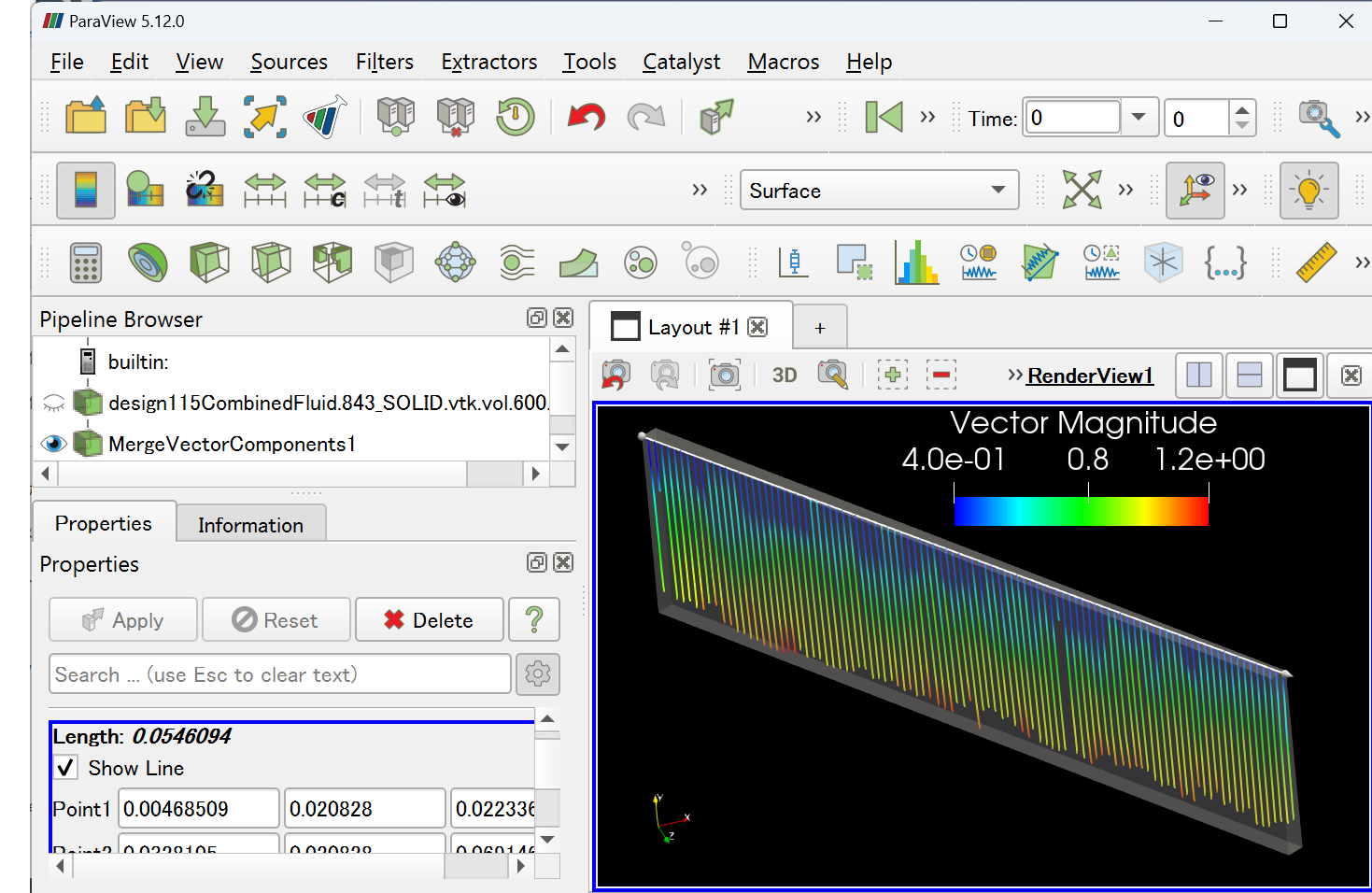
I considered the Merge Vector Components filter and the stream tracer is now visible.
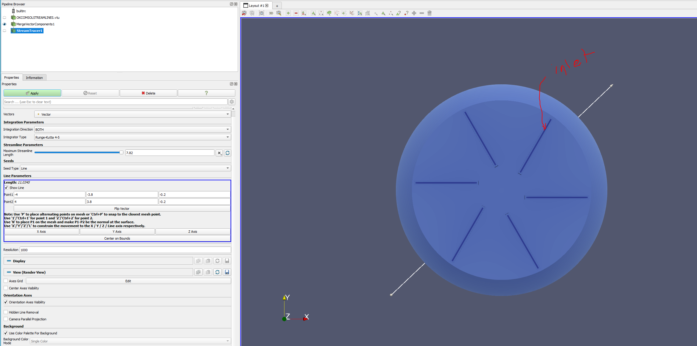
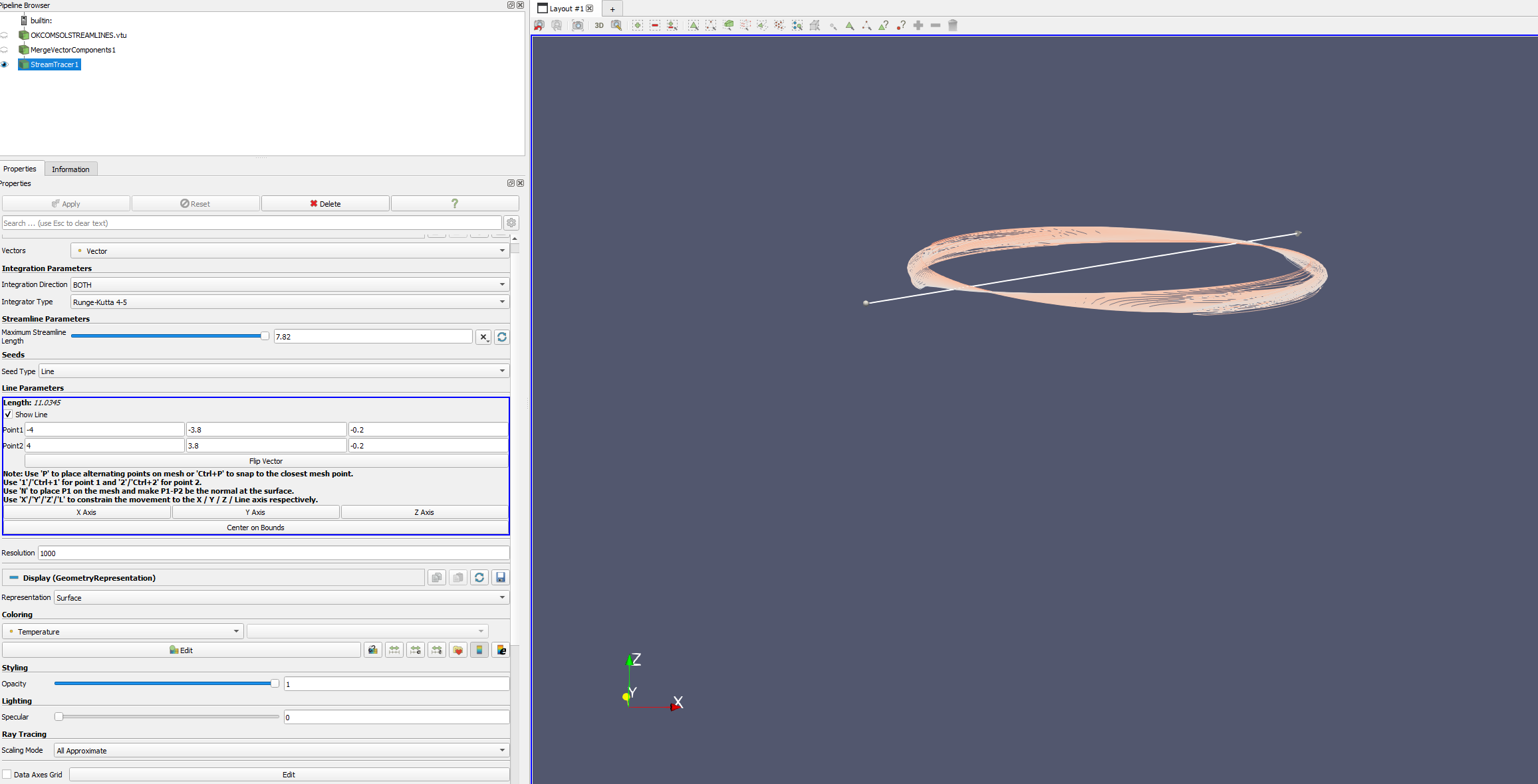
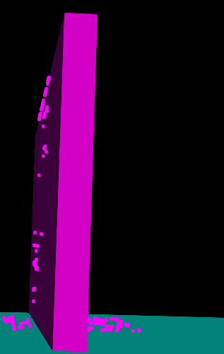
However, I don’t find the streamlines correct. In fact, I want to select my 6 inlets and then see how the streamlines would be inside the fluid domain. Not sure what I see as streamlines right now and how to increase the number of streamlines (not length)
Is there a way to select a specific surface or surfaces and see how the streamlines would evolve from there?
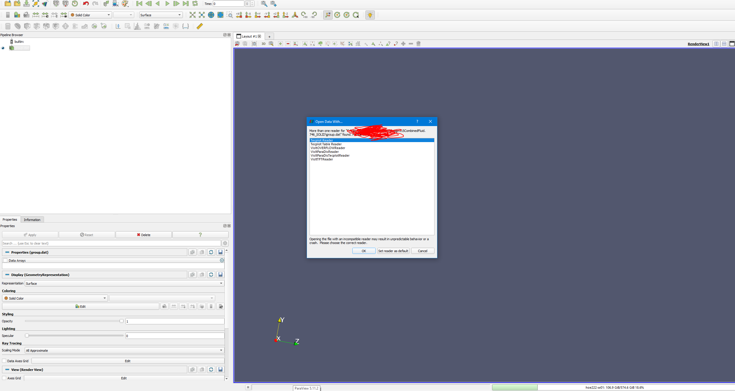
I am not sure what data format you are using, but it is most likely not supported by ParaView. You need to provide a file format that ParaView supports.
I have 6 similar domains as the shared VTK file which I grouped them with my main fluid domain. The issue is about extractselection function. I am not able to define points only on the inlet surfaces. It selects other points around the inlets. Any thoughts?
If the line is correctly aligned with the inlet’s face, I believe we can draw streamlines. In this case, you can easily align the endpoints of the line by using the ‘P’ button or ‘Ctrl+P’.