
20-node hexes. Note that the edges are rendered as broken lines at the locations of the mid-edge nodes. Is this expected? Is there a setting to control this behavior?
@PetrKryslUCSD – I mentioned this a couple years back:
The workaround, provided by @utkarsh.ayachit, is to
…add a pass through filter like Calculator or AddFieldArrays and then render that as wireframe while rendering the original dataset as surface.
@utkarsh.ayachit I’ve been thinking about this again. Since, as @martink mentioned in the linked post, “it is impossible to fix using the approach [ParaView is] currently using” - would it be possible to simply change the approach ParaView uses for rendering “Surface with Edges” to instead render surfaces and edges separately with the latter rendered as wireframe objects? At least as far as higher-order elements are concerned - the (2x ?) performance hit may not be that big a deal as the current approach doesn’t really work as intended for them. What are the drawbacks here?
FWIW, I’ve really found the workaround to produce exactly what I want - to the extent that I only have a single Favorites filter – the AddFieldArrays filter which I use only for this specific purpose. It’s become my most-often used filter (not hyperbole, I use it more than even WarpByVector). I don’t even know what the AddFieldArrays filter actually does - other than “it’s the filter that allows ParaView to render higher-order elements properly.”
@GregVernon I agree that wireframe and surface with edges should show the same edges from a user stand point. If this has a cost, an option could be added. In any case, we would need to investigate and add this feature, which may not be trivial.
Although in principle it makes sense that surface with edges should show the same as wireframe, I caution that there is a good reason the implementation is different between the two, and it is not just the speed of rendering. Just as surface with edges has some speckling issues that wireframe does not, drawing a wireframe on a surface has depth order issues. Check out this comparison between the two.
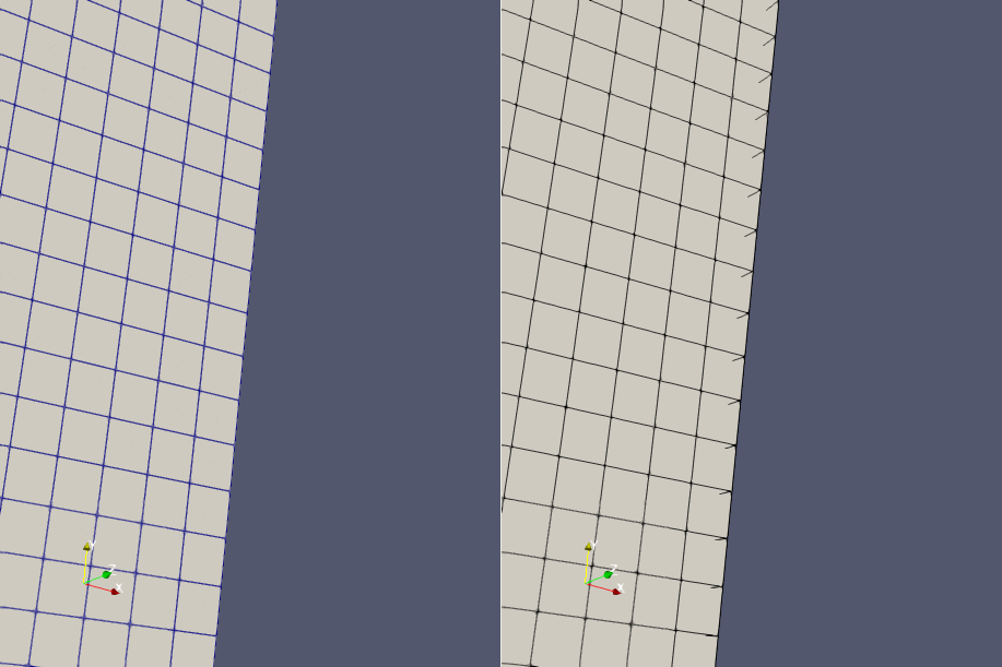
The image on the left is surface with edges. The image on the right is a wireframe drawn on the surface. With the wireframe, you can clearly see some of the edges in the back drawing through in the front. The general problem is that when drawing the two separately it is difficult to determine what should be in front when they are on the same surface.
I’m not saying we shouldn’t use this approach for nonlinear elements. The occasional poking out of edges is not as bad as the consistent speckling. But we should retain the current mechanism of surface with edges when not rendering subdivided surfaces even if that means inconsistent implementation.