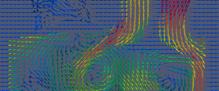
I am trying to make animations over time of a velocity field slice, similar as done in my attached example
video test|video .
At the moment we do plots and animation like this with Star-CD where we can define a fixed spacing grid of the glyphs, so these glyphs are every timestep at the same position even with changing bounds of the geometry (e.g. piston moving up and down in ICE-applications).
I tried the glyph filter in paraview on a slice, but couldn’t manage to get a satisfying result. There are different options for the glyph mode: Bounds based, surface sampling, every nth point … but none of these works well for me, because the mesh, slice surface and the bounds are changing over time and therefore the glyphs are new located every timestep. I need a solution to sample a plane with a glyph spacing of e.g. 2mm in x-direction and 2mm in y-direction. Is there any possibility right now maybe with glyphs with custom source?
Instead of slicing your data, try creating a Plane source covering where the slice would be. Set the X Resolution and Y Resolution parameters to the grid size of glyphs you want. Unfortunately, the Plane source does not have a nice 3D Widget to place it like the Slice filter does, so you will have to enter the coordinates by hand. Set Origin to one of the corners (say the “lower-left”). Set Point1 to one of the adjacent corners (e.g. the “lower-right”) and Point2 to the other adjacent corner (e.g. the “upper-left”).
Once you made the plane, use the Resample With Dataset filter to put the velocity field on the plane. Set the Source Data Arrays to your 3D dataset and Destination Mesh to the plane you just made.
Now just add the Glyphs to the plane. Set the Glyph Mode to All Points since you presumably already defined the spacing with the Plane resolution parameters.
thank you so much! I am getting closer to the desired results, but it is still not exactly how i want it, because the glyphs outside of the cut velocity field are also shown. I only want the glyphs inside this region. Maybe it works with a threshold on the glyphs?
I’m not sure what you mean by “outside of the cut”. If you mean values that are outside of the bounds of your volume, then you can Threshold by the vtkValidPointMask field that Resample With Dataset generates.
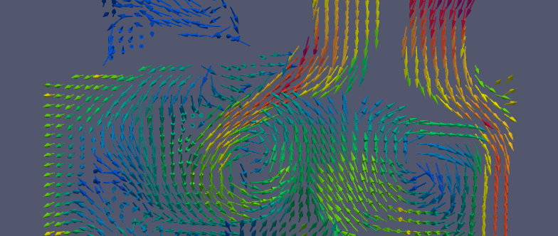
oh man thank you, you were right. I didn’t set to all points… Now i finally get the desired results! Thank you so much
But i need the threshold in the end and set the minimum value to 0.0001 because all the glyphs outside my domain get the values 0.