Good afternoon, I think this is a typical problem but I want to know how I could measure the flow rate of my simulation. I was looking for information but I only found that:
Integrate value filter for the inlet surface.
I don’t know if that gives me what I am looking for and how to know it.
Hello.
This is indeed a standard problem. Custom postprocessors like CFD Post has built-in calculating functions to get mass flow averages, integrals etc. ParaView, to my knowledge, doesn’t have this function so you can only do it manually. First and simplest way is to create a target surface like just slice or something curvilinear + thresholds to limit it’s bounds, then use Surface Normals and Calculator filters in series to compute rw=Density*(Velocity.Normals), then integrate with Integrate variables. It will only formally compute the sum of FaceArea*Variable, but inspecting the table for your rw variable column you will find the mass flow through the slice.
Although this method is simple, it’s not convenient because you must create this additional pipeline and then search the table for rw variable (datasets in CFD modeling has lots of variables so if you selected them all you will have a very long table header in Integrate Variables result). Also you will only get the mass flow. To calculate mass flow or area averages you will need to add more filters. Even if you use the custom filter, as I know, it’s not editable so you cannot just add new averaging functions (may be custom filters are editable in newer ParaView versions, sorry, I don’t know).
If you need intensive averaging for many variants and you want to get result as fast as possible and be able to add new functionality relatively easily, you can make a script. I attach my simple script, but you need to customize it for your variables. To use the script, select the target surface (like slice) in pipeline, then run the script from Python console. This is made for ParaView 5.2 (newer versions doesn’t support our “semi-hardware” RDP).
Hey,
i post it into that topic because its the same topic, if its not ok remove my post and i will start a new topic.
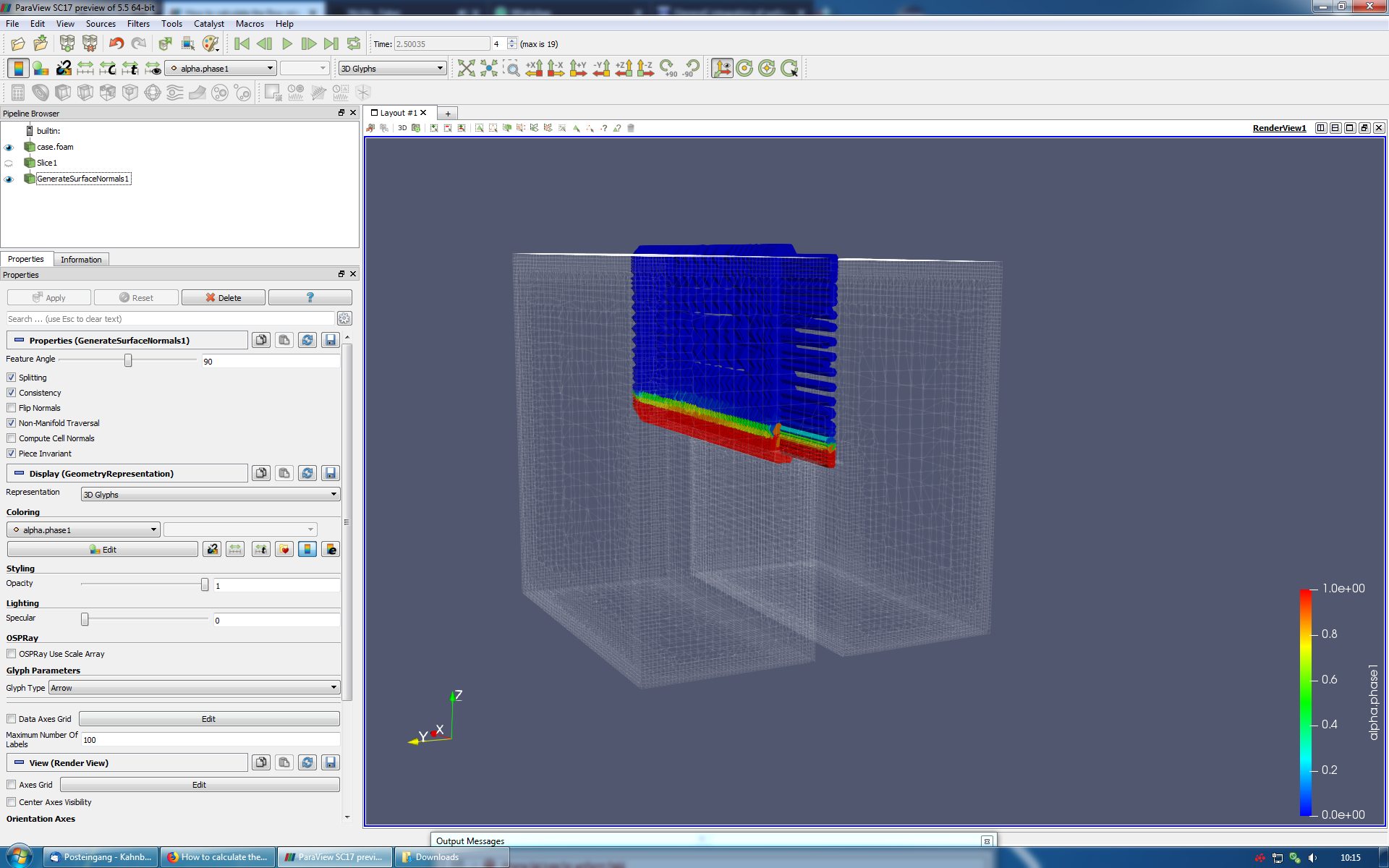
i have to calculate the mass flow over a threshold in a multiphase simulation. I create a slice at the threshold, and then the GenerateSurfaceNormls, but the Glyph are pointing to the side. Why the dont point in the normal direction ?
There is a screenshot below, showing the glyph.
Hello. I think, there is still no built-in function for the “function
calculation”. You may use Calculator filter to introduce the specific
flow variable(s) with Integrate Variables after it. Later will just
summarize AreaVariable over the mesh region you apply it to. So you
will need something like PhaseVolumeFractionPhaseNormalVelocity in
Calculator filter. Integrating it will give the sum of
PhaseVolumeFractionPhaseNormalVelocityCellArea that is the phase
volumetric flow through the selected mesh face (surface zone).
If you have an orthogonal face, just use the X, Y or Z velocity. But
if it’s not the cese, you will need the “costom” normal velocity. For
this, apply Surface normals to selected mesh zone first. It will give
you the Normals variable. Then use the scalar multiplication
(Normals.PhaseVelocity) as the PhaseNormalVelocity in expression above
or introduce an additional calculator filter with
(Normals.PhaseVelocity) and name the Result as PhaseNormalVelocity.
Please note that some things will only work properly with the
particular array types (surface or volume zones) and with only single
block. You may use the Extract Block filter to extract exactly the
volume region you need, then Slice it and feed integrate on this
slice.
@Antech
Hey Andrew,
sorry for my late replay.
I tryed to follow your guide, but i did not make it. I watch a few videos on youtube, how to use the calculator, it does not really fit to my problem.
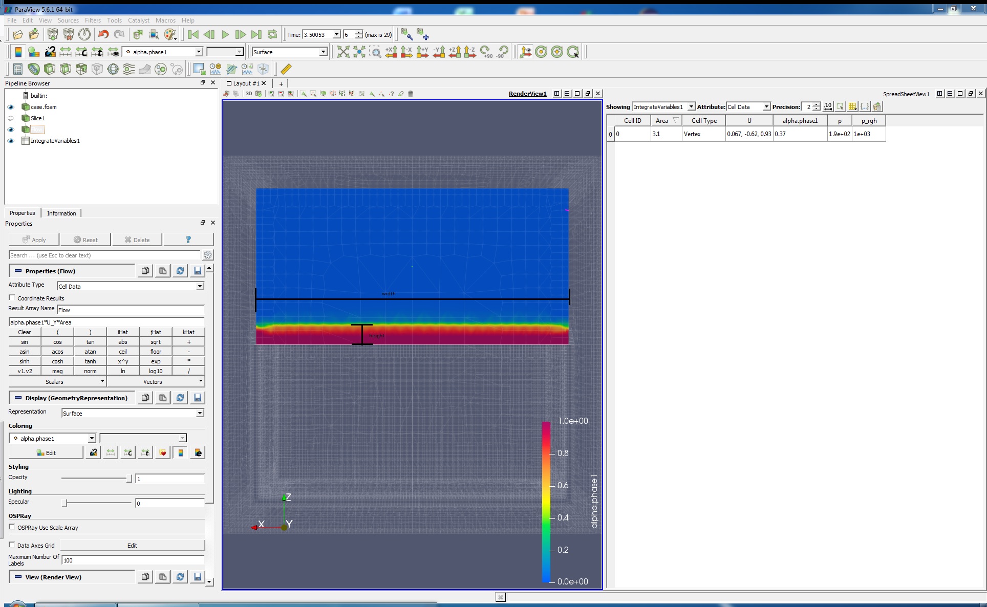
At the first attempt, i calculate alpha.phase1 * U_Y * Area
For the equation Q [m³/s]=v [m/s]*A [m²], i need the Area where the alpha.phase1 is over (for example 0.85).
Can i use the calculator to make an if instruction or something like that ?
Best regards
Kai
EDIT:
I have tried a little more.
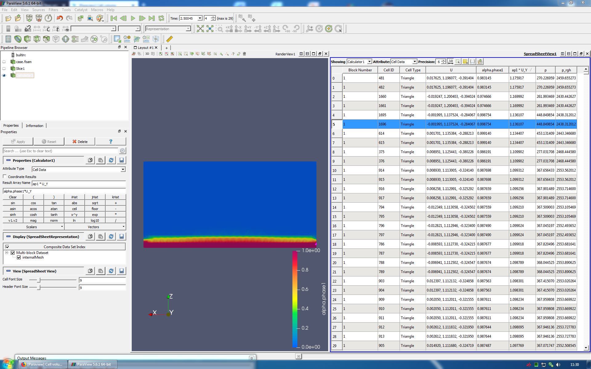
Like you write, i use the calculator to calculat the alpha.phase1 * U_Y direction.
This time the result columen add to the Spreadsheet.
How i get the Area of every Triangle at the Slice ?
I like to use alpha.phase1 * U_Y * Area of the specific triangle.
Would that work ?
Hello, Kai. If I get it right, you need alpha.phase*U_Y in calculator.
You may name the result Flux (usually, flow is absolute). It will
produce the [m/s] result because aplha.phase is [m3/m3]. Integrating
it (Intagrate variables), you will have the flow of the phase in
[m3/s] in “Flux” column in the Spreadsheet vie of Integrate variables
filter.
In addition to my previous message. Sorry, forgot this… If you need
to accoun for only regions where some conditions are met, use the
Threshold filter at the control surfece. Select alphs.phase as
variable and set min/max values (for example, min=0.86, max=1.0 or
just max=10). It will produce an array of faces that correspond to
your condition. Apply the Calculator to get the phase Flux in [m/s],
then Integrate variables (in integrates by the area) to get the phase
flow through the part of your control surface where the phase volume
fraction is greater that 0.85. If you need to apply the same filter
set to many surfaces, use Python script or Custom filter in GUI
(select the part of your pipeline and use the Custom filter in menu,
AFAIR).
Hey @Antech,
once again sorry for my late answer.
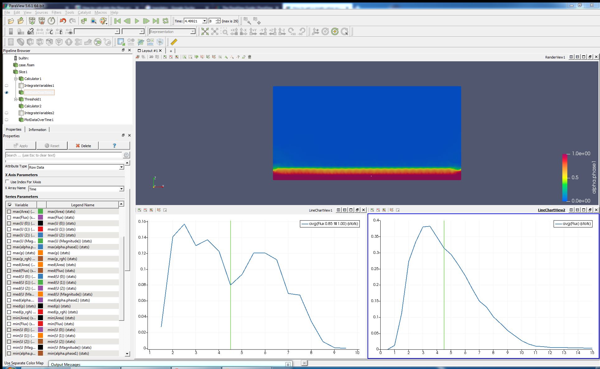
First thank you for your detailed answer. I think i got it.
At the picture, i compare the flux of a.p1 with the threshold of a.p1 0.85 to 1.0.
Hello.
I have a post-processing problem.
I need to calculate the average mass flow at a particular location (in the screenshot i drew a line at that location)
There is screenshot below showing the location. mass flowrate|690x359
Hello, you just need to do like in the video, you calculate magU then instead of extract block you will choose your slice and apply the filter integrate variables on it!
Thanks for the explanation. Using Integrate Variables on a slice or cross-sectional surface is definitely one of the most reliable ways to calculate flow rate in ParaView. [deleted]
