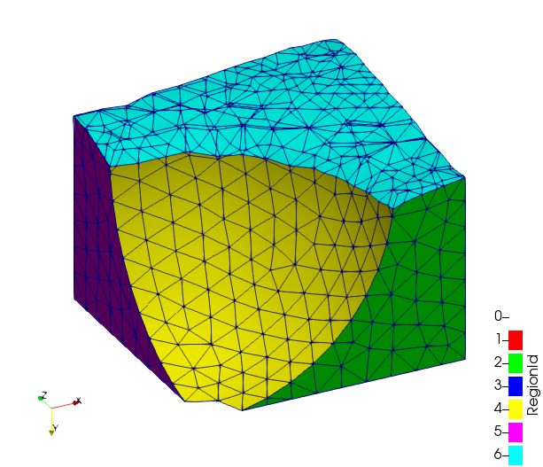
By isoSurface, I mean iso-contour of VOF=0.5. (Earlier, we have clipped the domain by VOF=0.5)
Or can we do like this:
Saving only isoContour of VOF=0.5 as .nas file and loading it into ICEM along with solid portion (which is a separate .nas file) and filling the space under the isoSurface with liquid?
Kind note: In my domain, solid is a block of sphere and the fluid contains liquid at bottom and vapor at top which are separated by isoContour of VOF=0.5.
There is a way to separate bounding surfaces for each part using the Generate Surface Normals filter based on a feature angle. Would you see the attached state file and outputted nastran file? test_clip3.7z (1.6 MB)
As described in the last post, I have applied the procedure to generate surface normals for the solid block also.
But, after generating GroupDataSets (maybe here I am doing mistake!!), by applying Programmable filter I do not see any elements in ICEM.
I request you to please see the attached state file that I have made from your suggestions and the generated .nas file. There is some mistake near MergeBlocks3
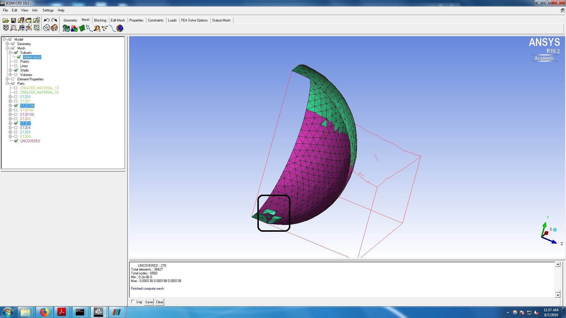
But when the surface.nas file is loaded onto ICEM, it is not generating parts separately for each bounding surface, which was the case eariler. Now, some bounding surfaces appear to have combined.
Could you please let me know how to rectify this.
Also shown in black rectangle, are the “added faces” under Subsets under Mesh. If I unselect “added faces”, empty region is observed. Are these added faces got created due to mesh size specification?
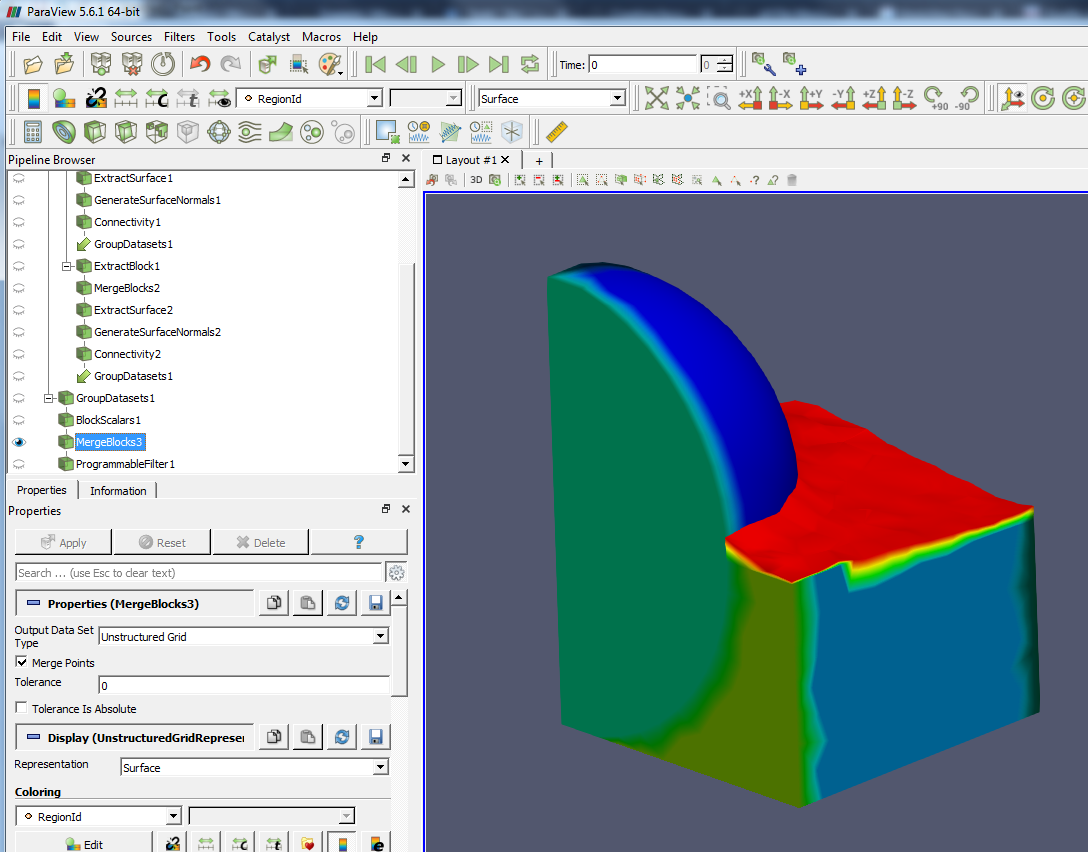
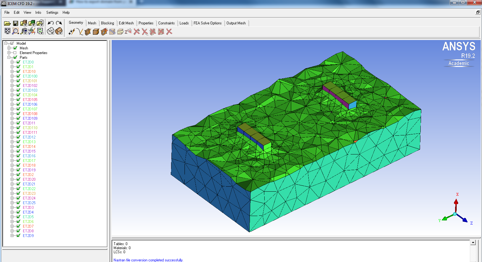
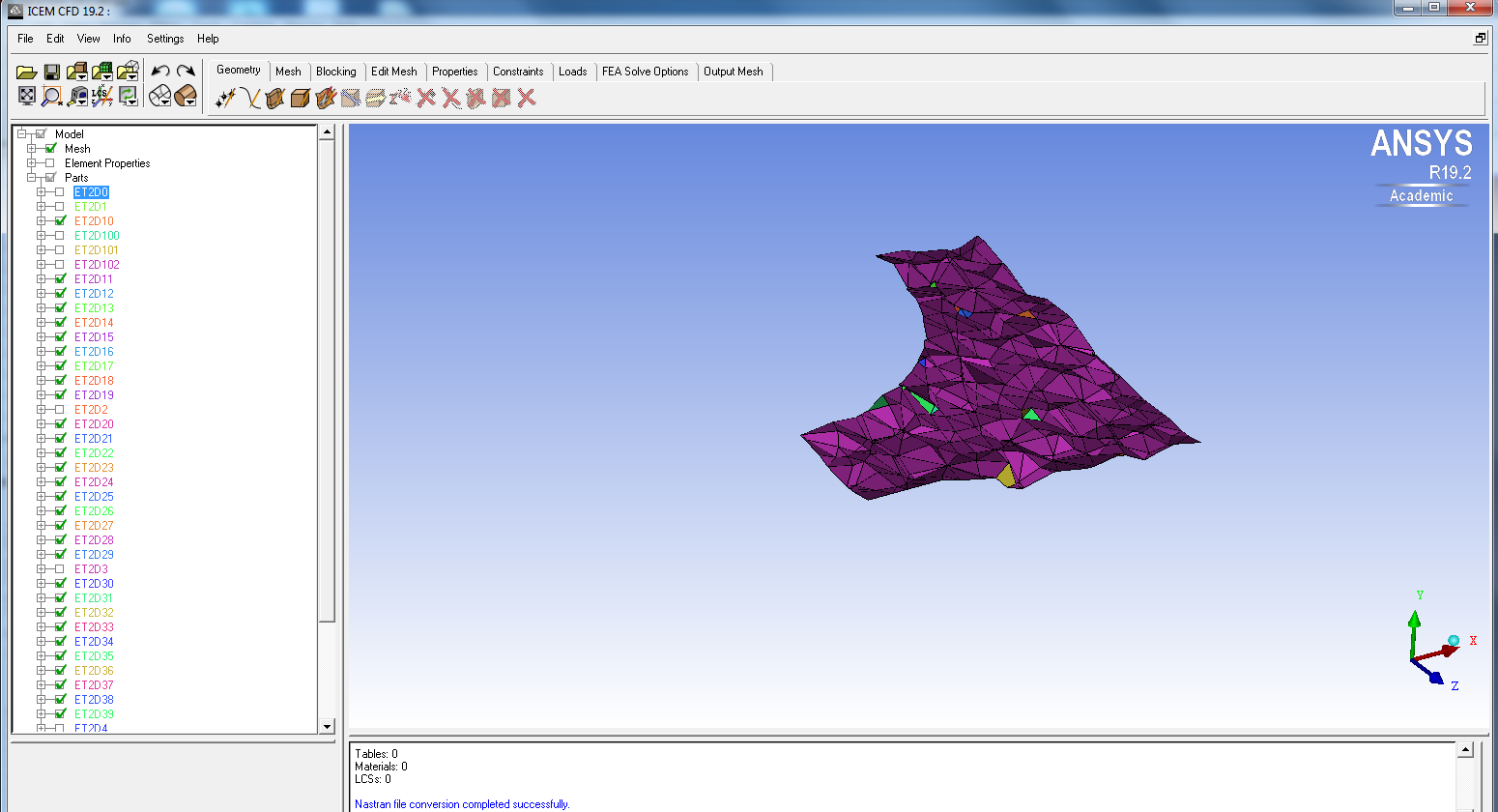
Please see the below picture, in which Ensight Case Gold files are loaded onto Paraview. Here, if I use the filter Extract Block, I can see the different bounding surfaces. But, when we load the .cas file into paraview, we can not see these surfaces separately even after using the filter “Connectivity”.
In the picture below, I am showing bounding surfaces in two screens in paraview, for the sake of clarity.
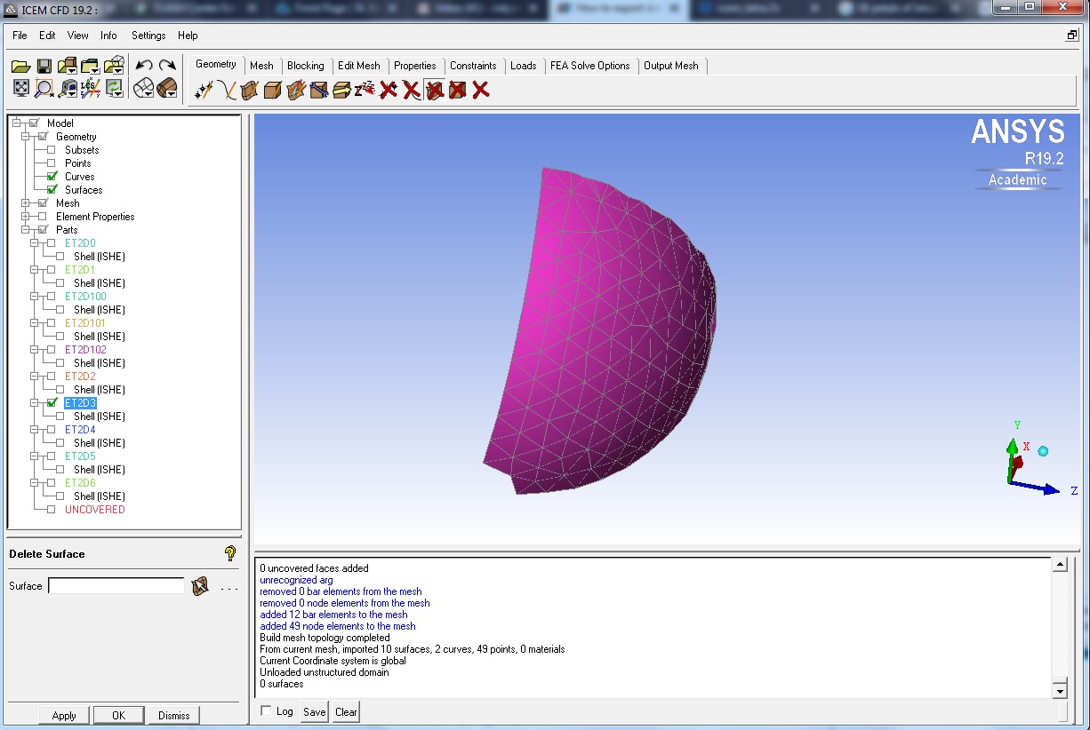
Three surfaces(in green, white and blue) of solid are adjusted between ET2D3 and ET2D100 as shown in the first picture.
May I request any suggestions in order to get the three sufaces (in green, white and blue) separately as shown in the second picture.
I think the following information might give more clarity:
Without doing anything after reading the .nas file (sent by you) onto ICEM,
I can see ET2D3 which is also shown when we select ET2D100.
But, ET2D100 do not differentiate green, white, blue portions as shown in the second picture of my previous post.
After generating mesh, then ET2D3 and ET2D100 are sharing the surfaces- green, white and blue
If the lower edge criterion (ex: 0.1) is specified than the default value 0.2, "added faces” problem would be solved. And the way to divide parts exists in ICEM CFD as some common operations. To get the details, would you see the attached movie?
Thanks for sharing the movie. It would solve my problems.
But, could you please share what you have done from loading .nas file till the beginning of the above movie. Because, when I try to delete the ET2D3 as described in the above movie, the curves are also getting deleted.
I am just attaching pictures of my ICEM window how it looks like. It is different from what you have shown in the above movie (Under the Model tree: Mesh, Element Properties are present and under PARTS: Shell (ISHE) is present in my window, which are not seen in the movie that you have sent).
I request you to share the initial steps in the form of a movie. Thank you!
Before my recording the the above movie, I had apparently added curves to the ET2D3 part by
Repair Geometry > Build Topology
with default settings. Could you try to build topology at first?
You can ignore Element Properties and Shell (ISHE) under the Model tree, because they are special on FEA Solver and unreferenced in outputing into fluent format.
I am listing few more queries and requests here. I request your suggestions and help in these too.
As I apply the above said procedure to a different geometry containing Two solids surrounded by fluid: When I load .nas file into ICEM, it displays very large number of PARTS. I understand this is because of the number of common surfaces between solids and fluid (Extract Surface–> Generate Surface Normals --> Connectivity --> Calculator --> Group Data Sets).
Inorder to reduce the number of PARTS, is there a possibility for combining the common surfaces (either in paraview or ICEM) which are formed at the intersection (or junction) between solids and fluid. I request you to please see the attached picture and files containing paraView state file, in case if there is a way to reduce the number of PARTS seen in ICEM. If there is a scope for creating PARTS in ICEM from curves or points, I think I can reduce the number of PARTS to maximum of eight - two solids, one interface (vof=0.5), outer bounding surfaces. test9.zip (3.6 MB)
When the maximum dimension of the computational domain is around 5 microns, I found that ICEM CFD is not displaying the .nas file properly. Please see the below picture and the .zip file (as mentioned in point 1 above) containing the scaled down Fluent Case and pvsm files.
From the post #27, in which you have sent me: test_clip6.7z
I have changed the option in clip1 from vof(partial) 0.5 to 0.1 in paraview. Then I have read the .nas file into ICEM. Then also, it is showing so many smaller parts as can be seen in the picture below.
Can you please let me know how to merge all these smaller parts with ET2D8 which is the biggest surface that can be seen in the picture. Or, could you please explain me how to manage these smaller parts in ICEM.
Please find attached test_clip6.7z which you have sent me earlier.test_clip6.7z (1.6 MB)
If you have already had a CAD model, you should simply use ParaView just to make an iso-surface and export it to a STL file. That is, an iso-surface would be extracted using the Contour filter as shown in the attached state file and afterwards you need to go to File > Save Data… for saving this iso-surface geometry as a STL file. iso_surface.7z (1.7 MB)
Then in ICME CFD, you can merge your CAD model and the above STL file and also easily generate a mesh with the intersections between them. See the attached movie.
This is the quickest way I’ve found so far.
The problem that you mentioned is caused by rounding error. Therefore, the x, y, z coordinates should be written to Nastran file in exponent form within programmable filter. See the above attached state file.
1a) Could you please attach the state file containing “Contour Filter” as I could not find it from your previous post. Did you export the contour in STL format by loading Fluent data in Ensight Case Gold format?
1b) Also, my requirement is to delete the fluid portion above the iso-surface and to retain the solids as well as fluid below the iso-surface for meshing. I hope the movie that you have attached in the previous post would address it. I will try it. But, for that, I request the iso-Contour state file as mentioned in my query 1a.
1c) Could you please tell me how did you get the CAD model (geom.tin) which you have loaded into ICEM as shown in the movie of your previous post.
For the scaledDown domain (where you have corrected Programmable filter): Yes, now I can see the mesh and domain in ICEM for the scaledDown version as given in the state file of previous post.
1a) I apologize for my mistake. I updated the file attached (iso_surface.7z) in the previous post. Would you be able to check it?
1b) You can just right click on the unnecessary parts name of the model tree in ICEM CFD to delete them.
1c) The CAD model (geom.tin) was created from the outputted Nastran file by hand in ICEM CFD. For the sake of your testing, I have uploaded this too. geom.tin (63.0 KB)