Hello,
I have fluent case and data file loaded onto paraview.
I have done a basic operation in paraview to delete some portion of the domain.
Now I want to export this residual portion of domain into ANSYS or any other meshing software for further meshing.
Can anyone hlep me how to do this.
Thanks in advance!
vidyadhar
Welcome to ParaView, @vidyadhar
You may already be aware of the File -> Save Data… menu item. Select the result you want to export in the Pipeline Browser and choose this menu item. You can choose to export the data into a number of formats selectable in the Save File dialog’s “Files of type” popup menu. You will have to consult with the meshing software you intend to use to see if it loads one of these available file types.
HTH,
Cory
Thank you Cory,
I am working on it.
Regards,
Vidyadhar
Hello Cory,
Is it possible to export only the outer boundaries of the domain/geometry from paraview.
If so, can you please let me know. Will they be exported as a single entity?
I want to export the geometry as .STL or .wrl format.
Does “Export Scene” helps me. It is exporting in VRML format. Is it equivalent to .wrl ?
Thanks & Regards,
Vidyadhar
Hello Cory,
My domain contains both solid and fluid. But, when I save data in CGNS format, it is saving only fluid domain.
I mean when I open the .cgns file in ICEM CFD, I do not see solid part.
Can you tell me how to export solid region also.
Thanks in advance!
Vidyadhar
Sure. You can run the Extract Surface filter. That will produce a surface mesh that you can export to STL through the File → Save Data… menu issue. You can also export to CGNS through this same menu item.
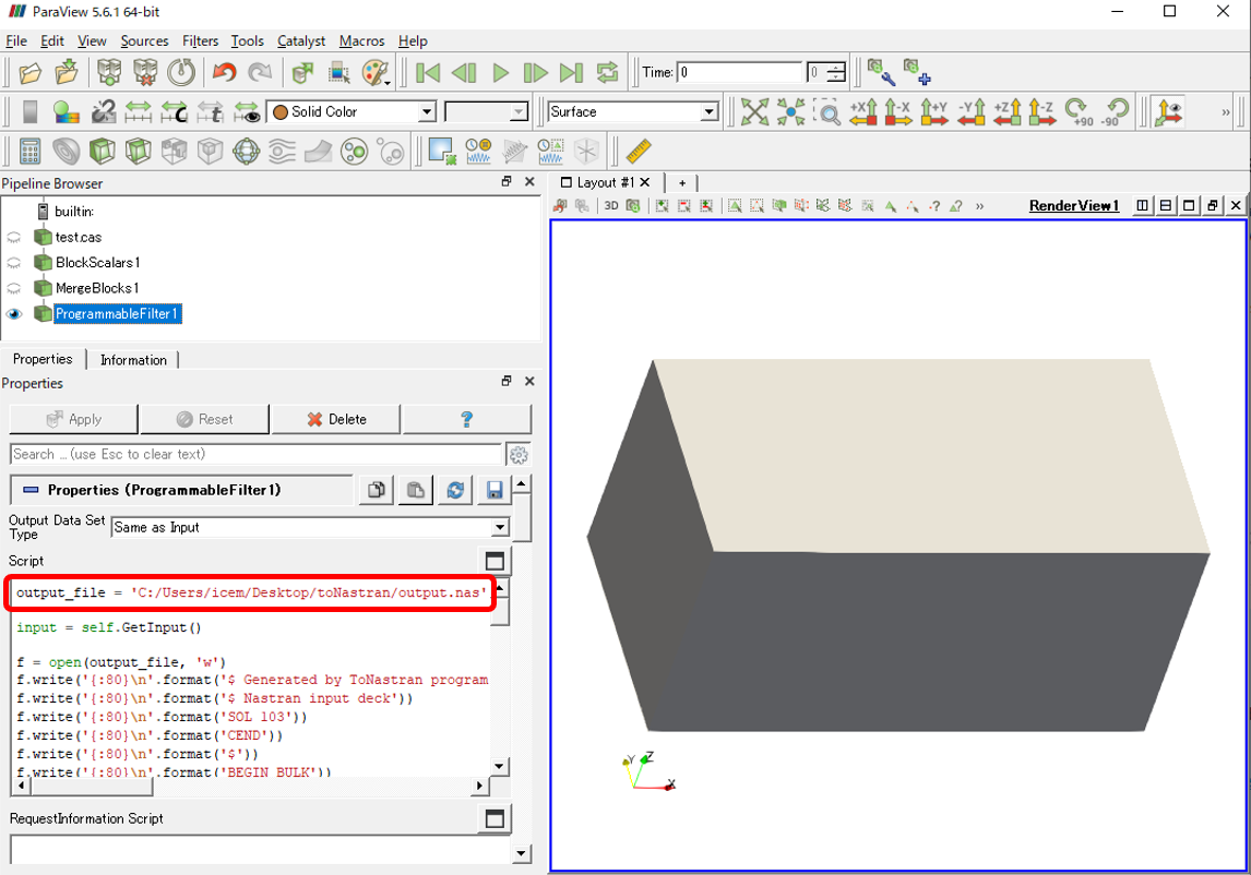
Nastran format is also supported in ICEM CFD, and you can easily export all of the domain in a Nastran file by using a Programmable Filter. Would you take a look at the attached state file for more details.toNastran.zip (41.7 KB)
output_file = 'your_path/output.nas'

input = self.GetInput()

f = open(output_file, 'w')
f.write('{:80}\n'.format('$ Generated by ToNastran program'))
f.write('{:80}\n'.format('$ Nastran input deck'))
f.write('{:80}\n'.format('SOL 103'))
f.write('{:80}\n'.format('CEND'))
f.write('{:80}\n'.format('$'))
f.write('{:80}\n'.format('BEGIN BULK'))
f.write('{:80}\n'.format('$'))
f.write('{:80}\n'.format('$       grid data              0'))

print('number of points in input is ' + str(input.GetNumberOfPoints()))
for i in range(input.GetNumberOfPoints()):
    point = input.GetPoint(i)
    id = i + 1
    f.write('GRID*{:>19}{:>16} {:<15f}{:<16f}*{:>7}\n'.format(id,0,point[0],point[1],id))
    f.write('*{:>7}{:>12f}{:>20}{:>32}{:8}\n'.format(id,point[2],0,0,''))

materialName = 'BlockIdScalars'
materialArray = input.GetCellData().GetArray(materialName)
print(materialArray)

mats = {}
for i in range(input.GetNumberOfCells()):
    material = int(materialArray.GetTuple1(i))
    mats.setdefault(material, []).append(i)

id = 0
for mat in mats:
    f.write('{:80}\n'.format('$       Volume element data for family'))
    f.write('{:6}{:10}{:64}\n'.format('PSOLID',mat,'       0       0       0'))

    for i in mats[mat]:
        id += 1
        cell = input.GetCell(i)
        cellType = cell.GetCellType()
        pntIds = cell.GetPointIds()

        if cellType == vtk.VTK_TETRA:
            f.write('{:6}{:>10}{:>8}{:>8}{:>8}{:>8}{:>8}{:24}\n'.format('CTETRA',id,mat,pntIds.GetId(0)+1,pntIds.GetId(1)+1,pntIds.GetId(2)+1,pntIds.GetId(3)+1,''))
        elif cellType == vtk.VTK_HEXAHEDRON:
            f.write('{:6}{:>10}{:>8}{:>8}{:>8}{:>8}{:>8}{:>8}{:>8}{:8}\n'.format('CHEXA',id,mat,pntIds.GetId(0)+1,pntIds.GetId(1)+1,pntIds.GetId(2)+1,pntIds.GetId(3)+1,pntIds.GetId(4)+1,pntIds.GetId(5)+1,''))
            f.write('{:6}{:>10}{:>8}{:56}\n'.format('',pntIds.GetId(6)+1,pntIds.GetId(7)+1,''))
        elif cellType == vtk.VTK_WEDGE:
            f.write('{:6}{:>10}{:>8}{:>8}{:>8}{:>8}{:>8}{:>8}{:>8}{:8}\n'.format('CPENTA',id,mat,pntIds.GetId(0)+1,pntIds.GetId(1)+1,pntIds.GetId(2)+1,pntIds.GetId(3)+1,pntIds.GetId(4)+1,pntIds.GetId(5)+1,''))
        elif cellType == vtk.VTK_PYRAMID:
#            f.write('{:6}{:>10}{:>8}{:>8}{:>8}{:>8}{:>8}{:>8}{:>8}{:8}\n'.format('CHEXA',id,mat,pntIds.GetId(0)+1,pntIds.GetId(1)+1,pntIds.GetId(2)+1,pntIds.GetId(3)+1,pntIds.GetId(4)+1,pntIds.GetId(4)+1,''))
#            f.write('{:6}{:>10}{:>8}{:56}\n'.format('',pntIds.GetId(4)+1,pntIds.GetId(4)+1,''))
            f.write('{:6}{:>10}{:>8}{:>8}{:>8}{:>8}{:>8}{:>8}{:>8}{:8}\n'.format('CPENTA',id,mat,pntIds.GetId(0)+1,pntIds.GetId(3)+1,pntIds.GetId(4)+1,pntIds.GetId(1)+1,pntIds.GetId(2)+1,pntIds.GetId(4)+1,''))

f.write('{:80}\n'.format('$  Geometry defaults data'))
f.write('{:80}\n'.format('$  Material Properties'))
f.write('{:80}\n'.format('$  Analysis type data'))
f.write('{:80}\n'.format('$  Load defaults data'))
f.write('{:80}\n'.format('$  Coordinate systems'))
f.write('{:80}\n'.format('ENDDATA'))

f.close()
Hello Cory,
Thanks for your suggestions.
I am able to export in STL format.
Thanks & Regards,
Vidyadhar
Hello Cory,
If I do File–> Save Data… whether the interior portion of the domain such as node/cell coordinates and other field variable data would also be saved in any of the possible output formats?
I have already deleted certain part of the original domain. Basically, I need
either
(i) I want to take back the mesh of the remaining domain to Fluent.
OR
(ii) save only the outer boundaries of the remaining domain and do meshing in other meshing softwares, then take the mesh to Fluent for further analysis.
I request you to let me know which of the above would be recommendable.
Thanks & Regards,
Vidyadhar
Hello Kyoshimi,
Thanks for sharing the Paraview State File and Fluent case file.
I have used them by loading Fluent case file sent by you.
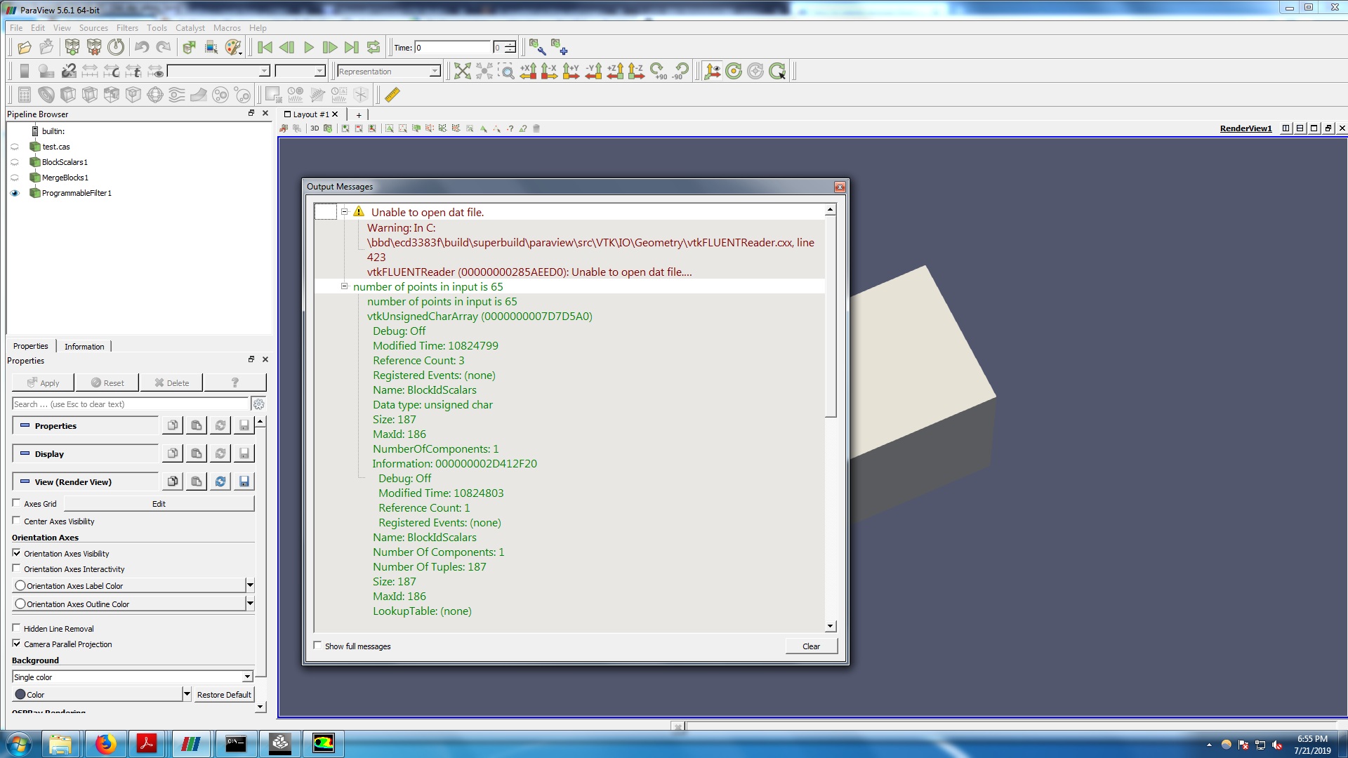
Please see the attached paraview picture showing Error messages. Could you please let me know if I have done anything wrong here (Regarding error messages)
.
Then how to open the generated “output.nas” file in ICEM CFD. Should I import as geometry or as Mesh.
I want to mesh the exported domain in ICEM CFD or ANSYS Workbench and take it to Fluent for further analysis.
Thanks & Regards,
Vidyadhar
IcedNastran Version 15.0
Input File D:/saveData/NASTRAN/toNastran/output.nas
Reading Input File …
Processing Executive List …
Processing Case Control List …
Processing Elements …
Processing Materials …
Processing General Parameters …
Processing Nodal Conditions …
Processing Element Conditions …
Processing Point Conditions …
Processing Properties …
Processing Explicit Properties …
1 Max Element ID 187
Translating Executive List …
Translating Case Control List …
Translating Materials …
Translating General Parameters …
Translating Nodes …
Translating Properties …
Translating Nodal Properties …
2 Max Element ID 187
Translating Element Properties …
Translating Attributes …
Translating Elements …
1 Max PID 1
Translating Load Attributes …
Writing Domain File …
Writing Gateway Attributes …
Writing Boco File …
Updating Families in Domain File …
start1: 33.0 seconds
finish1: 33.0 seconds
0.0 seconds to add_group
start2: 33.0 seconds
finish2: 34.0 seconds
0.0 seconds to write_domain
Cleaning up Memory …
Converstion Process Completed
Loading domain “project3.uns” …
Checking orientation:
** face at 0 14 32 has one volume**
** neighbor and no shell element**
** vt1 loc = 1 0 1**
** face at 0 14 33 has one volume**
** neighbor and no shell element**
** vt1 loc = 1 0 1**
** face at 0 20 37 has one volume**
** neighbor and no shell element**
** vt1 loc = 1 0 1**
** face at 0 20 44 has one volume**
** neighbor and no shell element**
** vt1 loc = 1 0 1**
** face at 0 32 37 has one volume**
** neighbor and no shell element**
** vt1 loc = 1 0 1**
** face at 0 33 44 has one volume**
** neighbor and no shell element**
** vt1 loc = 1 0 1**
** face at 1 20 42 has one volume**
** neighbor and no shell element**
** vt1 loc = 1 1 1**
** face at 1 20 43 has one volume**
** neighbor and no shell element**
** vt1 loc = 1 1 1**
** face at 1 24 28 has one volume**
** neighbor and no shell element**
** vt1 loc = 1 1 1**
** face at 1 24 29 has one volume**
** neighbor and no shell element**
** vt1 loc = 1 1 1**
** face at 1 28 43 has one volume**
** neighbor and no shell element**
** vt1 loc = 1 1 1**
** face at 1 29 42 has one volume**
** neighbor and no shell element**
** vt1 loc = 1 1 1**
** face at 2 12 13 has one volume**
** neighbor and no shell element**
** vt1 loc = 2 0 0**
** face at 2 12 31 has one volume**
** neighbor and no shell element**
** vt1 loc = 2 0 0**
** face at 2 13 39 has one volume**
** neighbor and no shell element**
** vt1 loc = 2 0 0**
** face at 2 31 39 has one volume**
** neighbor and no shell element**
** vt1 loc = 2 0 0**
** face at 3 13 14 has one volume**
** neighbor and no shell element**
** vt1 loc = 1 0 0**
** face at 3 13 45 has one volume**
** neighbor and no shell element**
** vt1 loc = 1 0 0**
** face at 3 14 21 has one volume**
** neighbor and no shell element**
** vt1 loc = 1 0 0**
** … and 80 more error messages …**
** faces are missoriented**
Loading solver parameters from project3.par.
Loading attribute data from project3.atr
Loading C:/Program Files/ANSYS Inc/v192/icemcfd/win64_amd/icemcfd/output-interfaces/nastran.bcinfo
Current solver is Nastran
Solver Nastran supports unstructured mesh.
Current Coordinate system is global
Element/property summary:
Volume Properties (Volume): 2 definitions, 187 elements
Tables: 0
Materials: 0
LCSs: 0
Nastran file conversion completed successfully.
Hello Kyoshimi,
Thanks for the reply.
I have changed the path before. Thanks again for more clear explanation.
But as I import the mesh into ICEM CFD the above messages are displayed.
When I perform the Check Mesh in ICEM CFD, many error messages are displayed such as:
77 problem volume elements were found for Uncovered faces
18 problems were found for Missing internal faces
etc etc…
Could you please let me know about them. Is it something that I have to manage in ICEM CFD to get rid of these messages.
Thanks & Regards,
Vidyadhar
Hi Vidyadhar,
Would you take a look at the attached movie, which shows a method to mesh in ICEM CFD?
icem_mesh.7z (3.8 MB)
Hello Kyoshimi,
Thank you very much for your help. I have seen the movie. I am grateful to you for your efforts in helping to solve my problem.
I will workout for my case(in which I have to delete certain portion of domain in paraview and take the remaining portion to Fluent for analysis) and get back to you, in case if I have further queries.
Thanks & Regards,
Vidyadhar
Hello Kyoshimi,
I have noticed three problems when I apply the procedure given by you for saving in NASTRAN format and creating mesh in ICEM. I, once again, request you to please help with these too.
I want to delete vapor cells in my domain using the ‘clip’ option in paraview. (clip --> scalar --> vof=0.5). But if I do so, paraview does not produce a closed shape. For this, if I use “cell Data to point Data”, I will get a closed surface.
But:
a) If I use cell data to point data, I think some changes are needed in the code given by you(Programmable Filter). Because it is saying “…object has no attribute Get Point”
b) I can not select “clip --> scalar” option if I use Merge Blocks!
c) Finally, if I import the mesh into ICEM, it is saying “Domain has a hole. Repair it”
I request you to kindly help me to solve the above issues. I am attaching the case and data file herewith. Could you please use these case and data files and share a video in case if you face the “repair hole” problem in ICEM.
Please find the attached zip file containing case and data files and .pvsm file
Thanks & Regards,
Vidyadhar

Hello Kyoshimi,
I am trying to modify the programmable filter code given by you to check if it works with the filter CellDataToPointData applied. However, I am running into problems. Can you please let me know how to solve it.
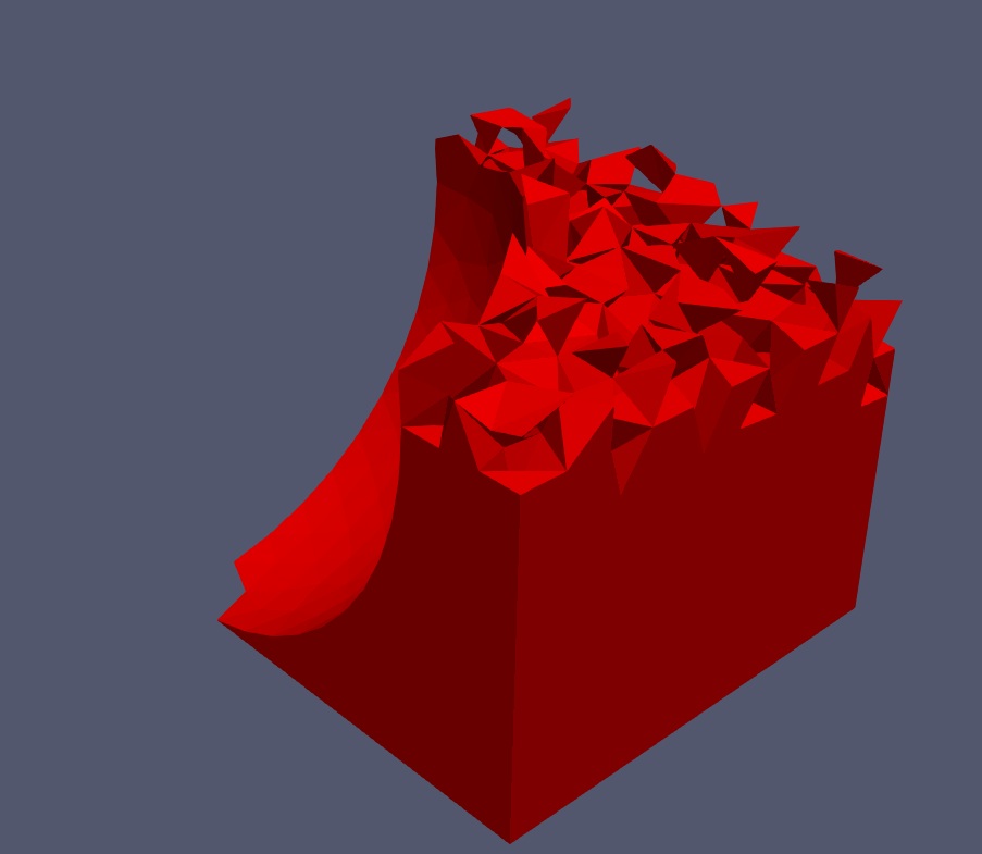
If I apply the programmable filter without cellDatatoPointData filter, it is not generating any data in the output.nas file as the interface appears to be open OR not closed as shown in the attached figure
.
Thanks & Regards,
Vidyadhar
Hi Vidyadhar,
Sorry for the late reply. I modified your state file to achieve the task. In addition, there is no need to change anything in the Programmable filter.
I put a state file here:
test_clip2.zip (1.9 MB)
I also share a video demonstrating how to mesh these data in ICEM:
Hello Kyoshimi,
Thanks again for the help.
I will go through the files.
But, it seems the video is not available on dropbox.
When I click the dropbox link, it says the file is not here anymore
Could you please re-share it. Or, if possible, could you please send it at https://www.dropbox.com/request/HiDI1nyJ3NHTS8aVCUrE (or) vidyadhar.kpm@gmail.com
Thanks & Regards,
Vidyadhar
Hi Vidyadhar,
I’m sorry the link was accidentally deleted. It has been restored.
Thanks
Hello Kyoshimi,
I am able to replicate the process you have done. I am very much grateful to you.
But still, I am little more greedy to know the following form you.
Now, I want to name the boundaries as I have done for the original geometry with the exception for the iso-surface which can be named as IsoSurface. In other words, I want to apply different boundary conditions in Fluent for different bounding surfaces. Particularly, at the iso-surface I want to apply a heat transfer boundary condition. But, as we are grouping all the uncovered faces into WALL group (as described by you), it is treated as a single entity.
My request: Is there a way to name the bounding surfaces of each BLOCK separately along with the created isoSurface. The iso-surface is very important for me, as I do not want it to be a part of any other PART(entity).
Could you please help me in this regard too.
Thanks & Regards,
Vidyadhar