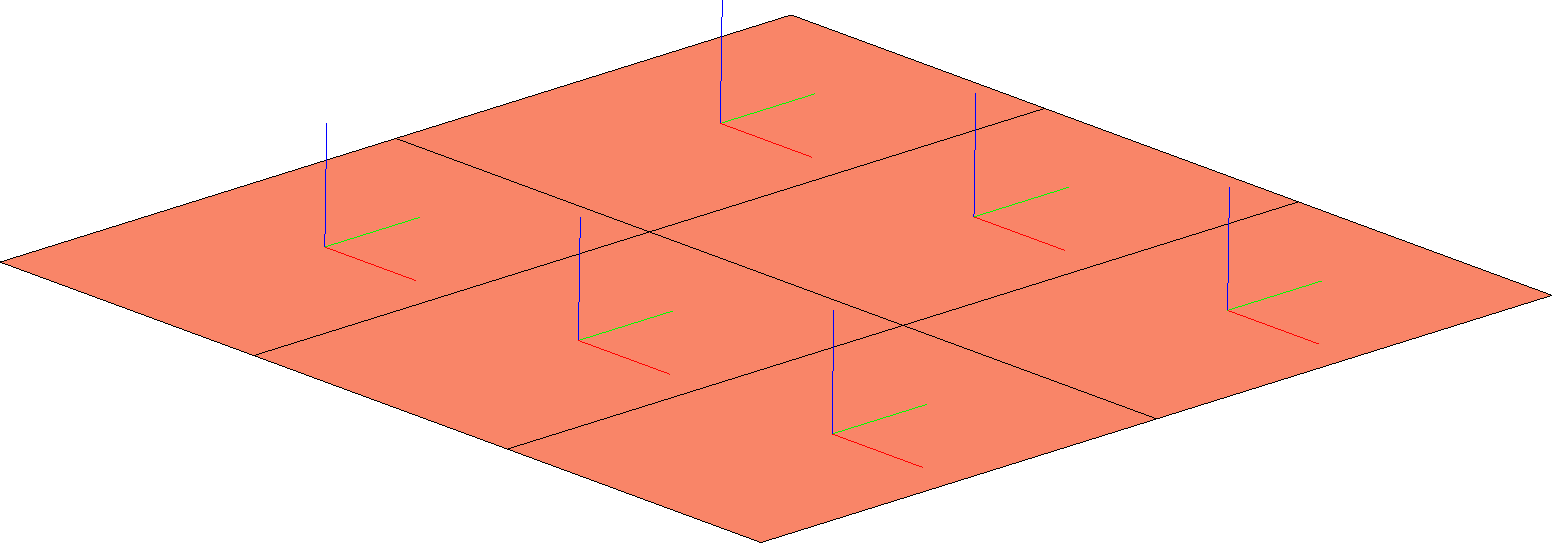
Is it possible in ParaView to display the orientation axes of shell elements (i.e. the local coordinate system of cells) to get a view similar to the picture?
Hi @Andrei,
You could try the “Normal Glyphs” filter to get the outward pointing normals to the surface.
As for the the other two directions, there seems to be some arbitrariness since any two orthogonal unitary vectors would do on the surface, are you looking for them to be oriented in the principal directions of the cells themselves? Do you have some local or global coordinate mappings you are using to define these directions? To make my question more precise, how are the other two directions defined in your data?
Dear @jfausty , thank you very much!
Your advice to use a “Normal Glyphs” filter solved the the core of a problem.
As for other directions, the figure shows SHELL-type finite elements, exported from the finite element analysis (FEA) program. I originally thought that information about how each shell’s local coordinate system is directed is also exported in ParaView. Maybe it is not. To restore local coordinate systems there can be two approaches:
- The X/Y axes are aligned with the axes of the global coordinate system (that is exactly what it is in this case).
- The X-axis is directed from the first node of the finite element to the second.
Obviously, in both cases, the X/Y axes are orthogonal to the Z axis and lie in the SHELL plane.
Hi @Andrei,
Glad to hear that the “Normal Glyphs” filter helped.
For the X/Y axes, do you have a data set that you can share? In order to give you the best answer I would like to try a couple things out myself.
Dear @jfausty , many thanks for the help!
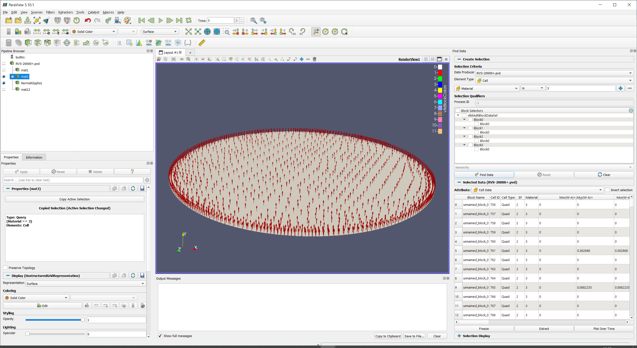
The model is posted on a file-sharing server at Oil_tank.zip - Google Drive . This is a testing finite element model of an oil tank for calculating its settlement (a geotechnical problem). The model was exported from the finite element program ZSoil (https://www.zsoil.com/). The model consists of finite elements such as SOLID, SHELL, BEAM. As an example, in the screenshot using Find Data → Extract, the elements of each type is highlighted. The SHELL elements in the question are material number 3.
Hi @Andrei,
Thanks for sharing the data. I have managed to download, open and work with it in ParaView.
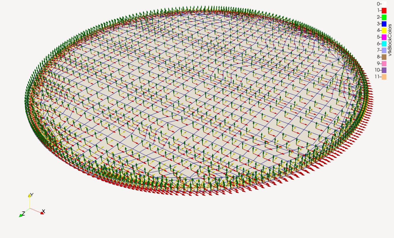
Here is a state file oil_tank_local_coords.pvsm (897.5 KB) where I propose the following for the X/Y glyphs:
- Use a “Cell Centers” filter on your extraction
- Use a “Glyph” filter on the output of the cell centers (by default it should make arrows pointing in the X direction)
- Use another “Glyph” filter on the output of the cell centers and use the “Glyph Transform” property in the properties panel to rotate the glyph by 90 degrees along the Y direction
This should give you approximately what you are looking for.
Dear @jfausty! Thank you very much for your help! Your solution works great!
Great! I’m glad it was helpful.