I’d like to postprocess my AirShaper simulation. The goal is to get mean pressure at the beginning and at the end of a inlet duct of a jet model and also mass flow through the inlet duct.
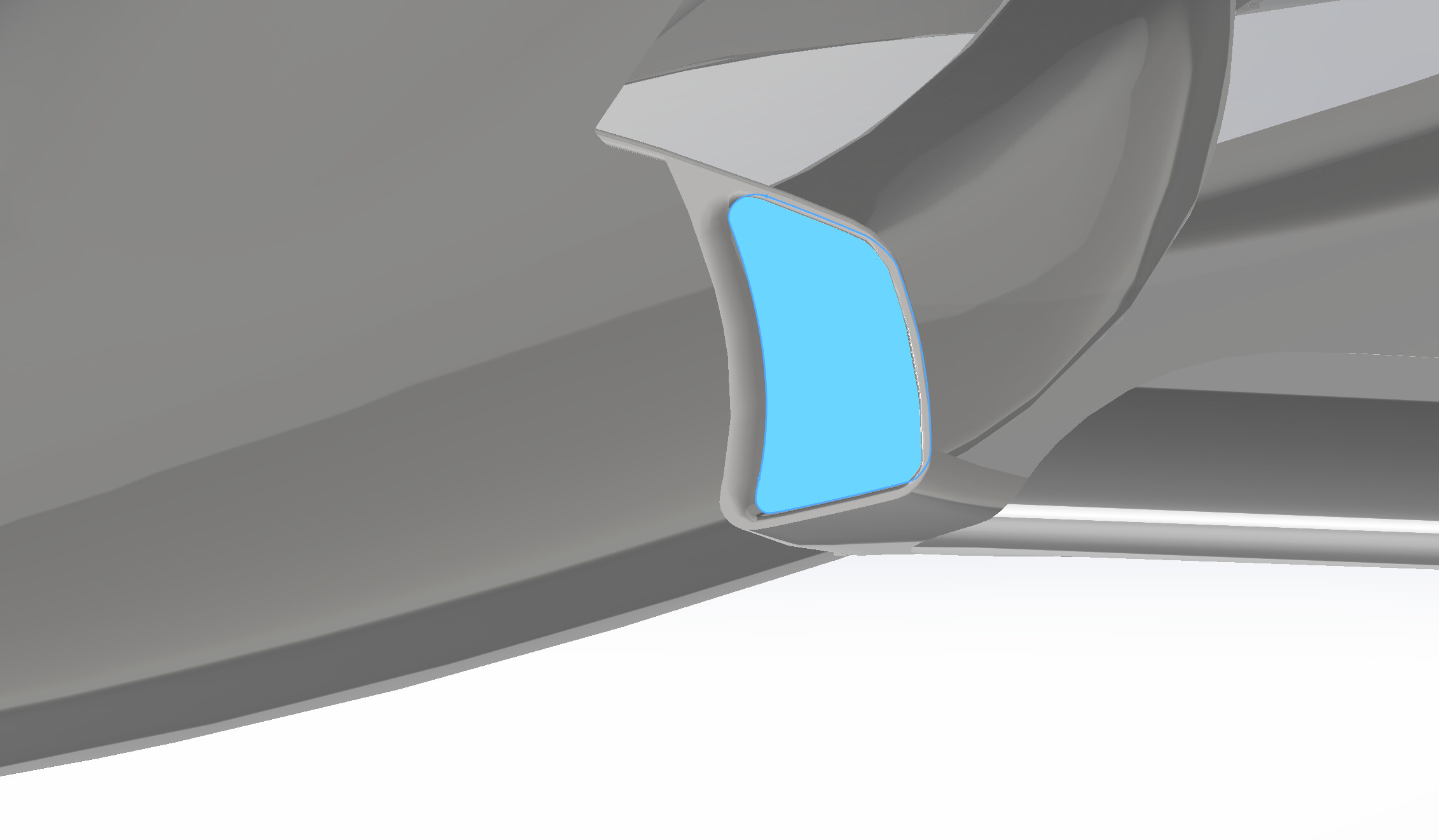
I started creating an aera from the cross section in at the beginning of the inlet duct in SolidWorks. I saved it as an obj-file and opened it into my already opened simulation data. I thought it would be positioned correctly as it was positioned in SolidWorks, but it is not. As you see on the screenshots is neither the sice of the area correct nor the position and orientation.
I wonder if there is a way to export and import area data with correct position from SolidWorks to ParaView. Or does somebody have another idea how to measure mean pressure and mass flow?
Would be nice if somebody could help me.
I export data from SolidWorks as STL. I tried Binary and ASCII. I select the desired coordinate system during the export process. Actually the plan was to directly import STL to the simulation, because when I click on “open” in ParaView there is “Supported Types” automatically selected. When hover over those types it says that “Supported Types” also includes “stl”. With “Supported Types” I can’t find my stl-files though. When I select “All Files” I’m able to find my stl-files, but it also produces the same problem with orientation etc. (using STL-Reader")
As I see obj-files with “Supported Types” I thought it might be the case that obj fits better. So I converted stl to obj with different converters (Meshmixer and some online converters) but it did not work out either as I posted.
If you think it is more a SolidWorks question I will no longer misuse this forum for this, I’m sorry. But do you maybe have another idea how to solve the problem with ParaView? It doesn’t have to be exactly these exported surfaces. If there is a way to somehow “construct” an area within ParaView that roughly fits into the inlet duct this would also be a solution.
This is caused by the extension which paraview expect to be lower case .stl. In any case, what you are doing is perfectly fine, you could also rename your file instead.
I select the desired coordinate system during the export process.
This is problably the problem, it looks like the plane and the mesh are not in the same coordinates system. You could try to transform the data in ParaView to fix that (using the Transform filter) but it would be better to fix that during the export in SolidWorks.
If you think it is more a SolidWorks question I will no longer misuse this forum for this, I’m sorry.
Dont worry, no problem at all. What I mean is that we may not be able to help you as the correct way to fix this is problably un SolidWorks.
If there is a way to somehow “construct” an area within ParaView that roughly fits into the inlet duct this would also be a solution.
You definitely can select the cells on the plane and extract them. I can help if you share the plane geometry.
This is caused by the extension which paraview expect to be lower case .stl. In any case, what you are doing is perfectly fine, you could also rename your file instead.
That hint was very helpful!
Unfortunately, I can’t share the plane geometry publicly. Also, the desired area is not part of the mesh internal mesh as it is a cross section from the duct. Would that be a problem for your extraction method?
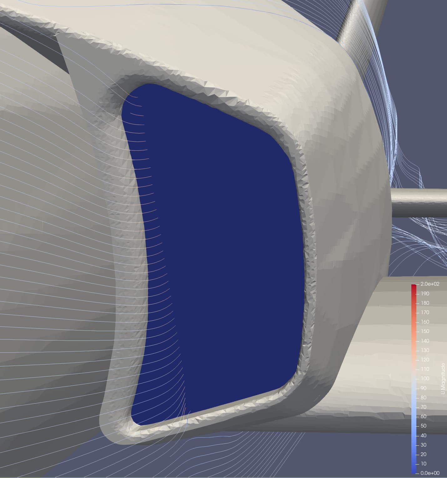
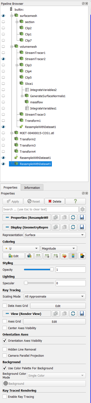
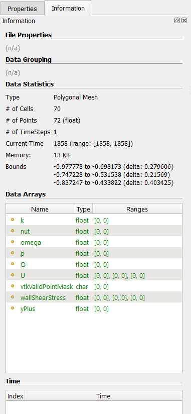
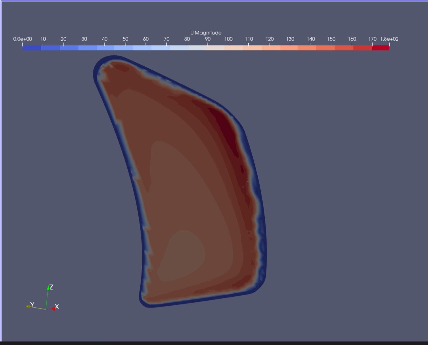
I managed to import the stl surface into the simulation. I positioned it with transform commands. It was only translated and scaled, so I assume that maybe AirShaper changed scale and position of the coordinate system. I resampled with dataset, using foam / internal mesh as source and the stl-surface as destination. Now I get zero speed (blue) over the whole surface eventhough the streamlines proof that this is not correct. I also tried changing the color map.
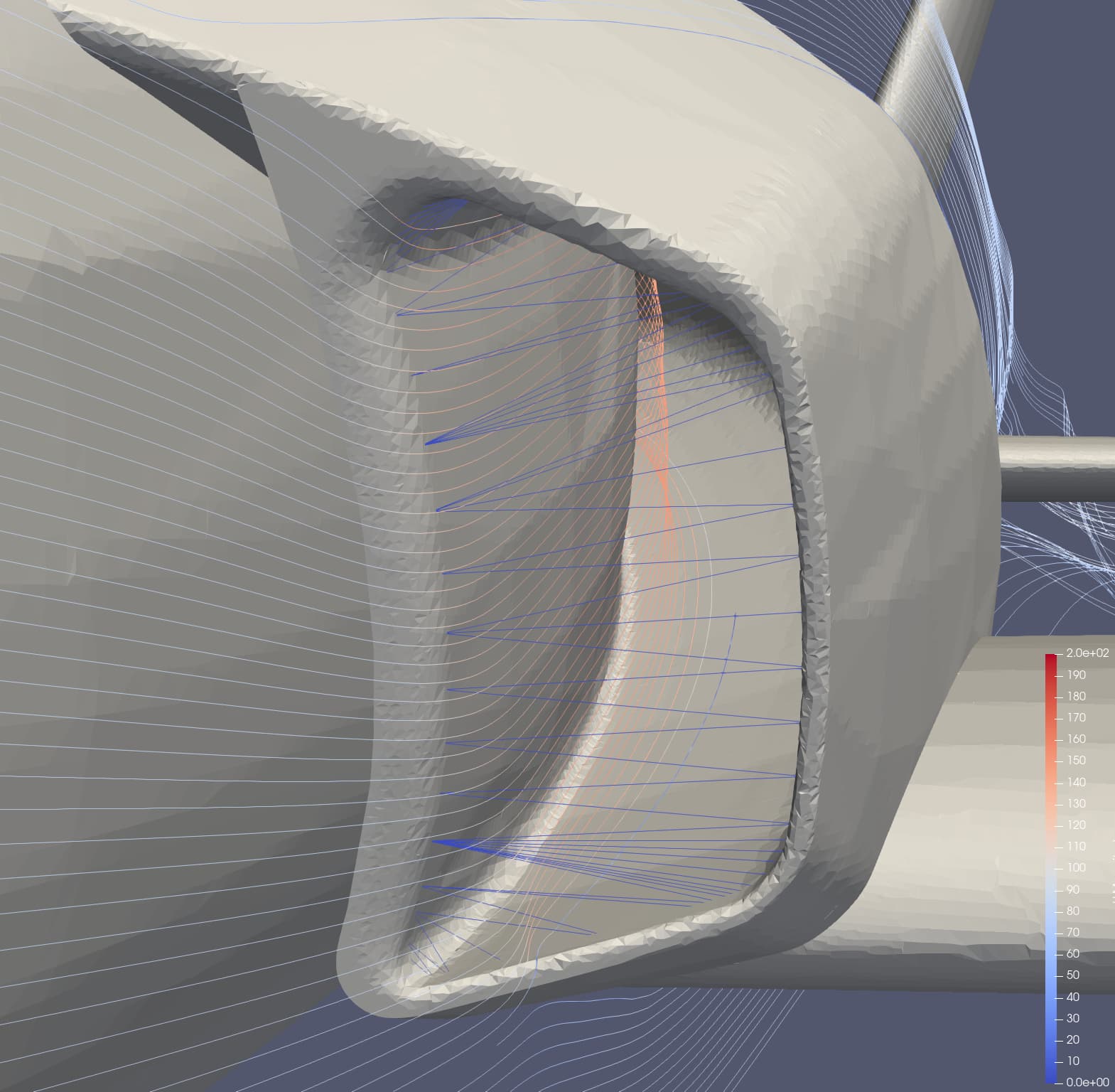
finally found it out. The problem was the mesh of the surface-stl which was too coarse (see last picture I sent with the “Wireframe” caption). After LoopSubdivision it seems work perfectly.