The hight of the first cell, is approximately 1.8e-7.
Why is that happening?
Using checkMesh everything is OK:
Checking geometry...
    Overall domain bounding box (-20.25 -15.5 0) (80.75 15.5 0.05)
    Mesh has 2 geometric (non-empty/wedge) directions (1 1 0)
    Mesh has 2 solution (non-empty) directions (1 1 0)
    All edges aligned with or perpendicular to non-empty directions.
    Boundary openness (2.277920031e-20 -1.87383777e-19 1.150632749e-16) OK.
    Max cell openness = 3.88755667e-13 OK.
    Max aspect ratio = 104.8966563 OK.
    Minimum face area = 3.197058684e-10. Maximum face area = 2.13787771.  Face area magnitudes OK.
    Min volume = 3.197058684e-12. Max volume = 0.0213787771.  Total volume = 49.87393779.  Cell volumes OK.
    Mesh non-orthogonality Max: 16.55199107 average: 3.159688271
    Non-orthogonality check OK.
    Face pyramids OK.
    Max skewness = 0.3359864834 OK.
    Coupled point location match (average 0) OK.
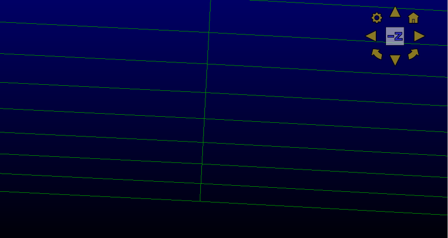
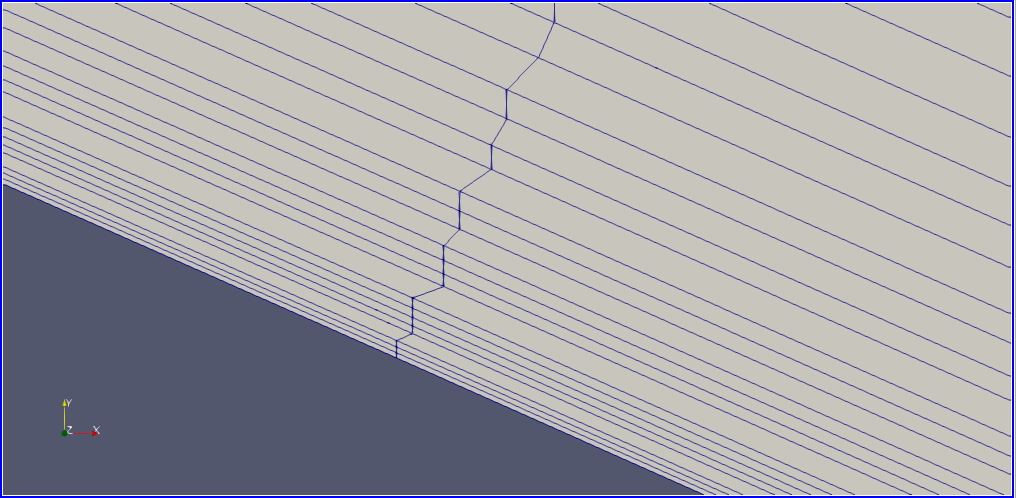
Well, I confirm that the issue is with Paraview since the mesh shows up properly in both gmsh and when I re-import it again in Pointwise as OpenFOAM grid.
First thought would be ASCII format file somewhere in the mix. But aside from that, if I understand it correctly the mesh is roughly 100 by 30 with cells as small as 1.8e-7. That is an e9 difference in scale while float only supports about e7 resolution. So yes it could be a float resolution issue.
In ParaView 5.9, there are new options to control coordinate shifting and scaling. Under the Display section of the properties panel for meshes, there is a new option called Coordinate Shift Scale Method. It defaults to “Auto Shift Scale”, which transforms coordinates once based on the bounding box of the data. When zooming in on the boundary layer, you want to change this option to “Focal Point Shift Scale” or “Near Focal Plane Shift Scale”, and the edges should look correct.
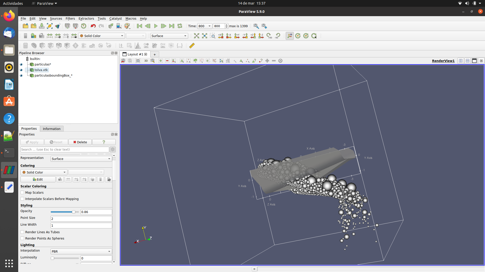
Hi, i have a similar problem.
When i move the mesh, the particles into the truck’s hopper move, but the mesh seems like dont move.
Please help me with this