I have a structured mesh which has a velocity field of a reservoir. In the central region of the reservoir, we have about 30 cells in the Y direction. However, at the time of creating the vectors (Glyph), there is no amount of vectors corresponding to the cells in the Y direction.
Does anyone have any suggestions?
The velocity vectors in the Z direction also do not appear, (or appear when they want), can this be due to the difference in order of magnitude? (order of magnitude at x = 1x10 ^ -2 and order of magnitude at z = 1x10 ^ -6)
t is a reservoir that has a narrowing in the central portion. The wide area has between 25 and 35 cells, but this number of vectors does not appear.
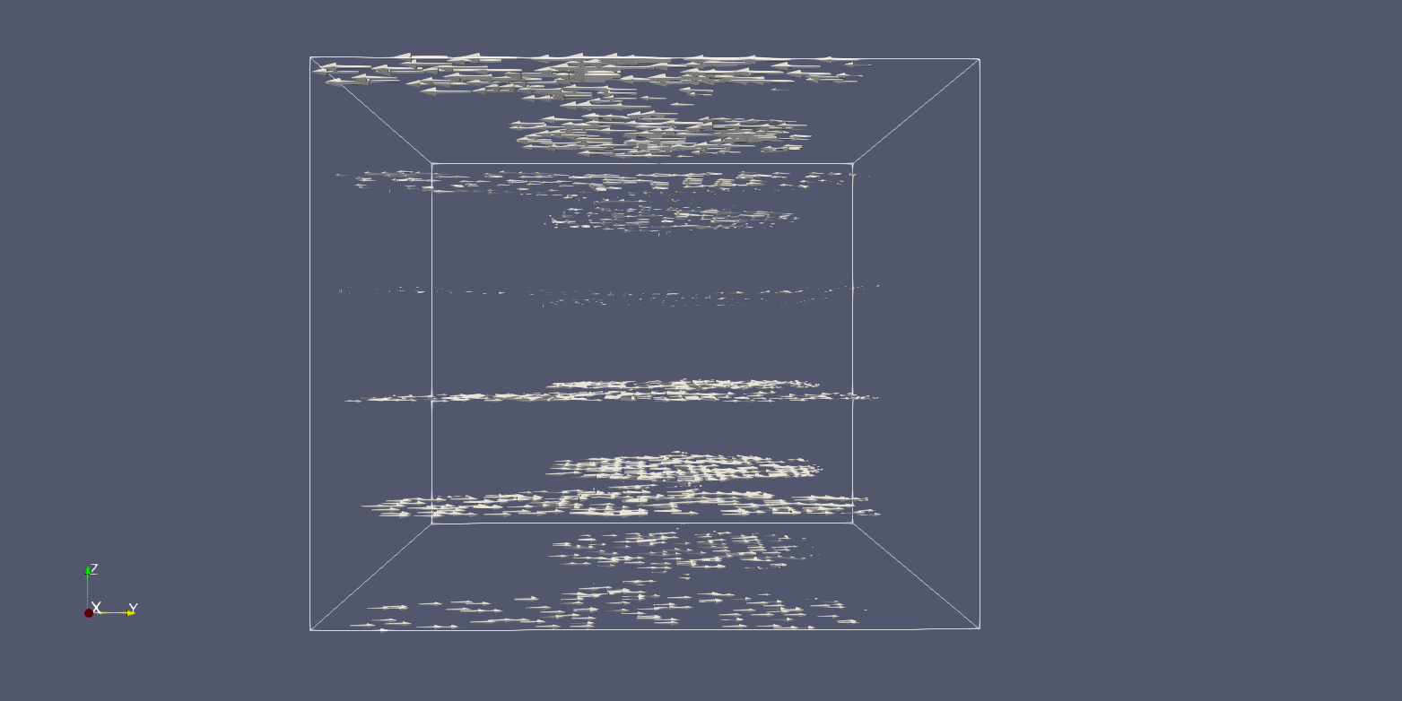
In this photo I sent, I added a wind to the east (right) portion of the reservoir, which generates a recirculation. In the left portion of the reservoir should appear vectors in the downward direction Z and in the right portion vectors in the upward direction Z.
In the VTK input file there are all values but no visualization appears.
To aid in the visualization of the layers, the “calculator” filter is applied in the Z direction (100x larger) because the difference between the layers is small (0.666 m, 1.333 m, 2.00 m, 2.666 m, 3.333 m, 4.000 m)