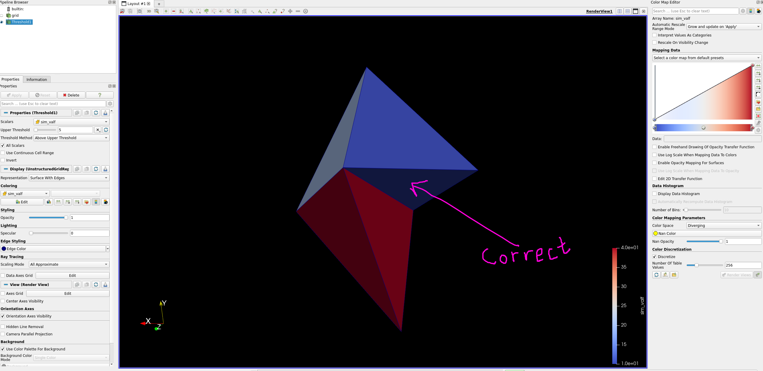
Below is an example that I made. The correct one is the thresholded one.
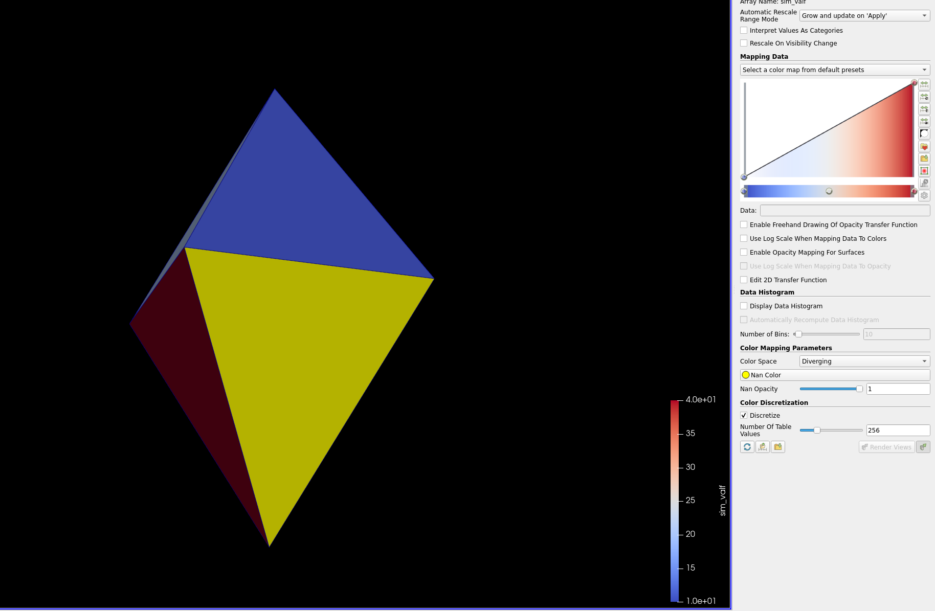
Original:
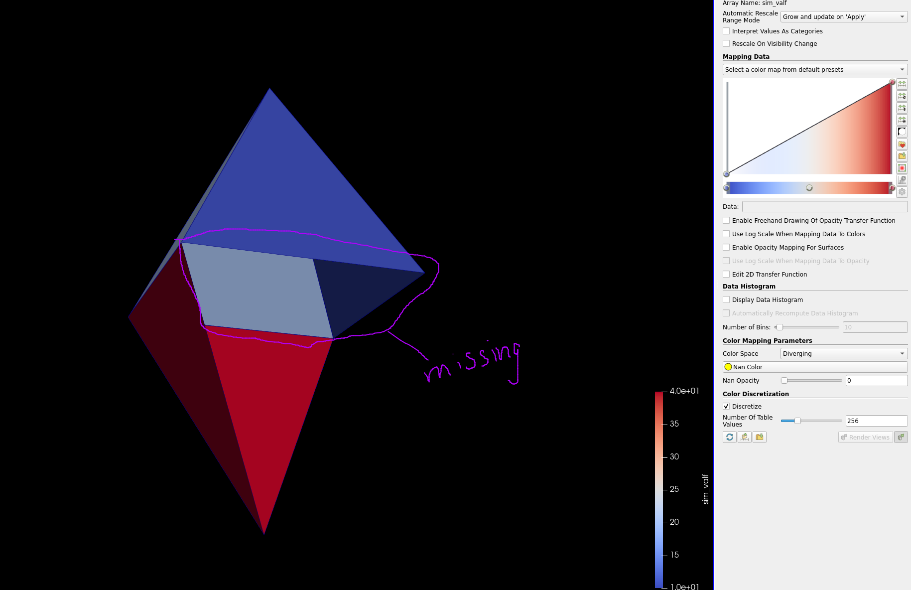
Setting opacity to 0 for nan; a face is missing:
Thresholding:
The thresholded version is correct.
Sample code:
// Vertices:                    0  1  2  3  4     5
    std::vector<float> _coordsX = { 0, 0, 1, 1, 0.5,  0.5};
    std::vector<float> _coordsY = { 0, 0, 0, 0, 1,   -1};
    std::vector<float> _coordsZ = { 0, 1, 0, 1, 0.5,  0.5};


    //                                       0       1     2      3      4     5      6     7      8       9     10     11     12
    // Faces                                 A       B     C      D      E     F      G     H      I       J     K       L      M
    std::vector<int> _faceConnectivity = {0,1,2, 0,1,4, 1,2,4, 0,2,4, 1,3,4, 3,2,4, 2,1,4, 3,2,1, 0,1,5, 1,5,2, 0,5,2, 1,5,3, 3,5,2};
    std::vector<int> _faceSize =   {3, 3, 3, 3, 3, 3, 3, 3, 3, 3, 3, 3, 3};
    std::vector<int> _faceOffset = {0, 3, 6, 9, 12, 15, 18, 21, 24, 27, 30, 33, 36};

    std::vector<int> _tetConnectivity = {0,1,2,3,  4,5,6,7, 0,8,9,10, 7,11,12,9};
    std::vector<int> _tetSize = {4, 4, 4, 4};
    std::vector<int> _tetOffset = {0, 4, 8, 12};

    float nan = std::nanf("1");
    std::vector<float> _valuesFaces = {10, 20, nan, 40};
    std::vector<float> _valuesVertex = {5, 10, 15, 20, 25,30};


    // create an explicit coordinate set
    mesh["coordsets/coords/type"].set("explicit");

    mesh["coordsets/coords/values/x"].set_external(&_coordsX[0], _coordsX.size());
    mesh["coordsets/coords/values/y"].set_external(&_coordsY[0], _coordsY.size());
    mesh["coordsets/coords/values/z"].set_external(&_coordsZ[0], _coordsZ.size());


    // add an unstructured topology
    mesh["topologies/mesh/type"].set("unstructured");
    mesh["topologies/mesh/coordset"].set("coords");

    mesh["topologies/mesh/elements/shape"].set("polyhedral");
    mesh["topologies/mesh/elements/connectivity"].set_external(&_tetConnectivity[0], _tetConnectivity.size());
    mesh["topologies/mesh/elements/sizes"].set_external(&_tetSize[0], _tetSize.size());
    mesh["topologies/mesh/elements/offsets"].set_external(&_tetOffset[0], _tetOffset.size());

    mesh["topologies/mesh/subelements/shape"].set("polygonal");
    mesh["topologies/mesh/subelements/connectivity"].set_external(&_faceConnectivity[0], _faceConnectivity.size());
    mesh["topologies/mesh/subelements/sizes"].set_external(&_faceSize[0], _faceSize.size());
    mesh["topologies/mesh/subelements/offsets"].set_external(&_faceOffset[0], _faceOffset.size());


    // add the data
    auto fields = mesh["fields"];

    fields["sim_valv/association"].set("vertex");
    fields["sim_valv/topology"].set("mesh");
    fields["sim_valv/volume_dependent"].set("false");
    fields["sim_valv/values"].set_external(&_valuesVertex[0], _valuesVertex.size());

    fields["sim_valf/association"].set("element");
    fields["sim_valf/topology"].set("mesh");
    fields["sim_valf/volume_dependent"].set("false");
    fields["sim_valf/values"].set_external(&_valuesFaces[0], _valuesFaces.size());