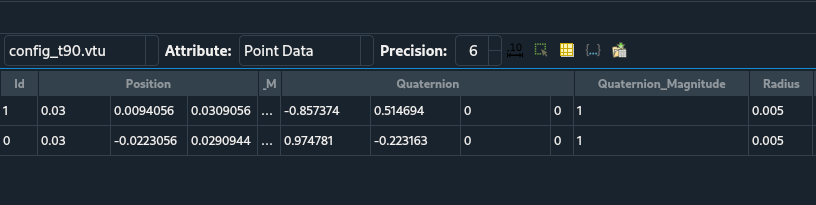
I am trying to visualize orientation of spherical particles. I have vtu files which has 4-component Quaternions in it, as can be seen in the screenshot. (or see the file: config_t90.vtu (1.3 KB) )
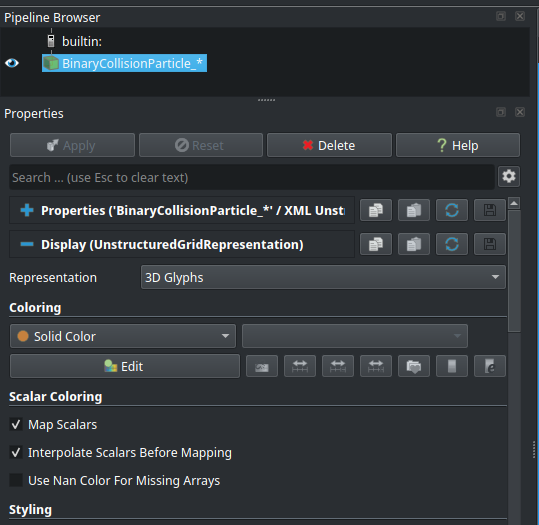
However, I am not able to properly visualize the orientation/rotations using it - it doesn’t change. I am using 3D Glyph for Representation, using Sphere as Glyph Type, Quaternion as Orientation Mode, and column “Quaternion” as Orientation vectors, etc.
Glyphs also looks really large in size. Setting radius and Scale Factor to 1.0 in Properties tab alone does not give true size. But setting raidus = 0.005 (true radius of particle in meter) in Display(GeometryRepresentation) tab makes it closer to true size. But still the overlap sometimes and is not perfect. What am I doing wrong here? Here is my state file for the same file : state_file.pvsm (296.0 KB)
Hi @mwestphal , thank you for your reply. Is the image you generated using the data I shared? could you share the script please?
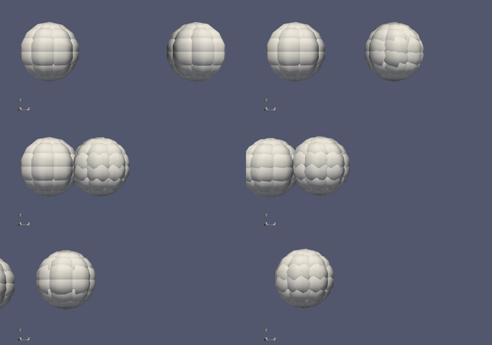
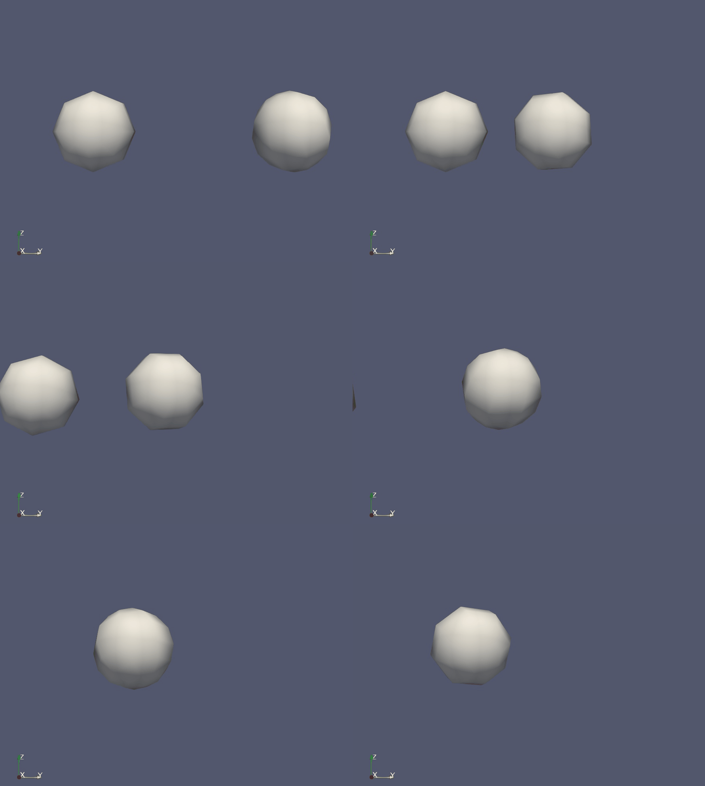
And about the sphere orientation, ParaView can actually do that. We just need to make low resolution Glyph. See an example below (here I used a vector to specify orientation)
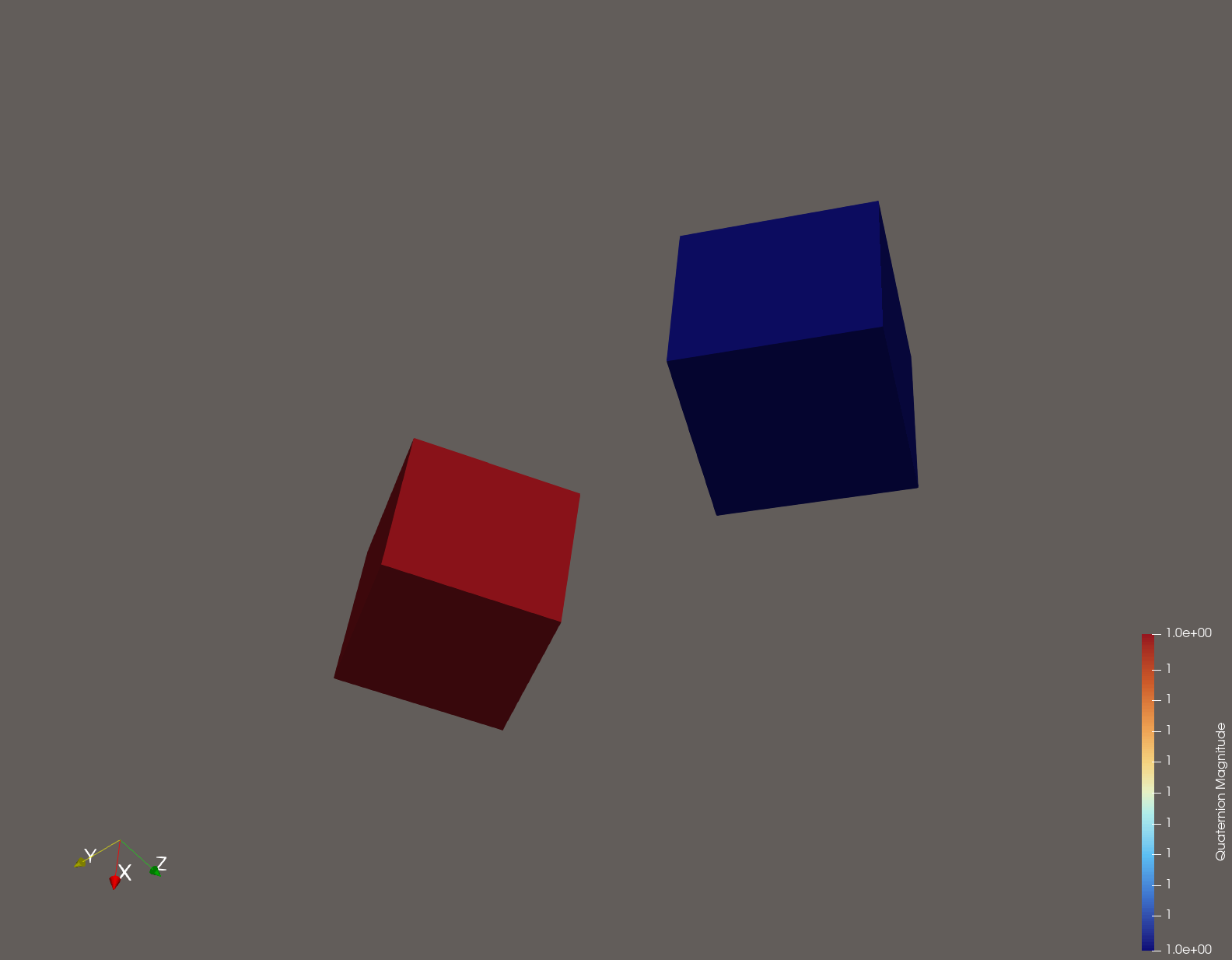
Another way is to color Glyph in different directions with different colors. See an example in my previous post. And about the scaling, when I use ScaleFactor=1, spheres are so big that they overlap each other. I am able to reproduce this still, using the same samples configuration files I shared. So, somehow my data needs a smaller value.
Thanks a lot, it works perfectly!
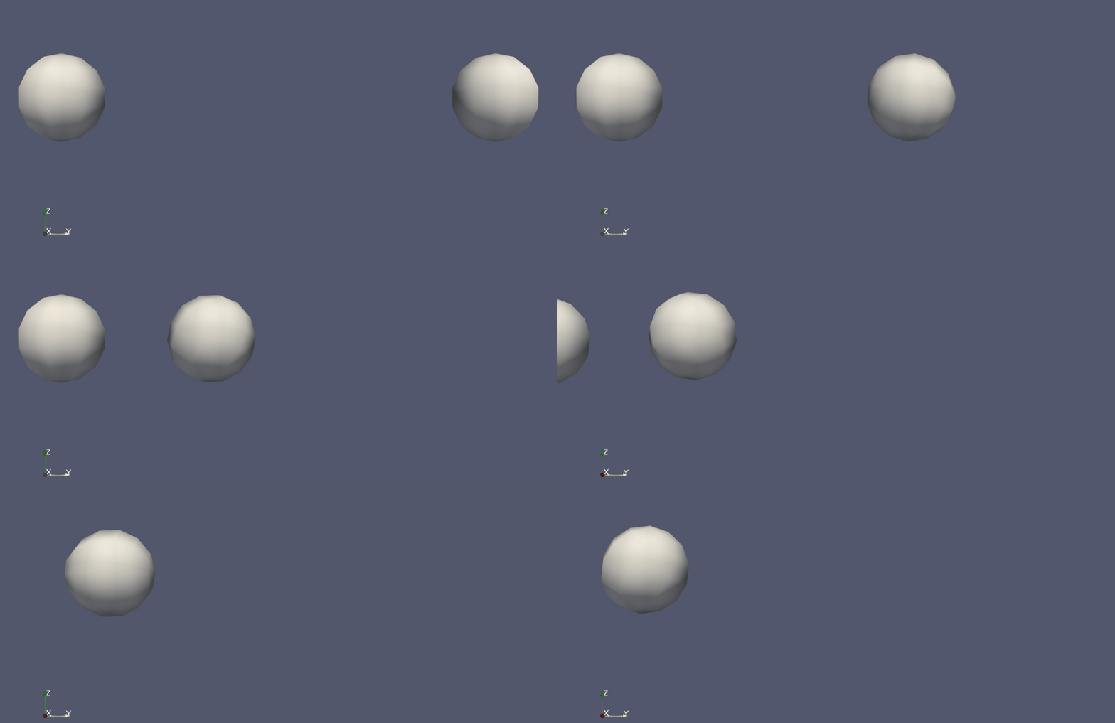
I think the missing part was not using the filter ConvertToPointCoud. I have been doing the normal Glyph directly to the data. And again, using low resolution in Glyphs, I can see the rotation as expected!
Meanwhile, I had also got it partially working. Problem was, running the ParaView version I compiled locally ‘Orient’ button ( ) was not visible. Downloading the binary directly, fixed it, among many other weird things I had.
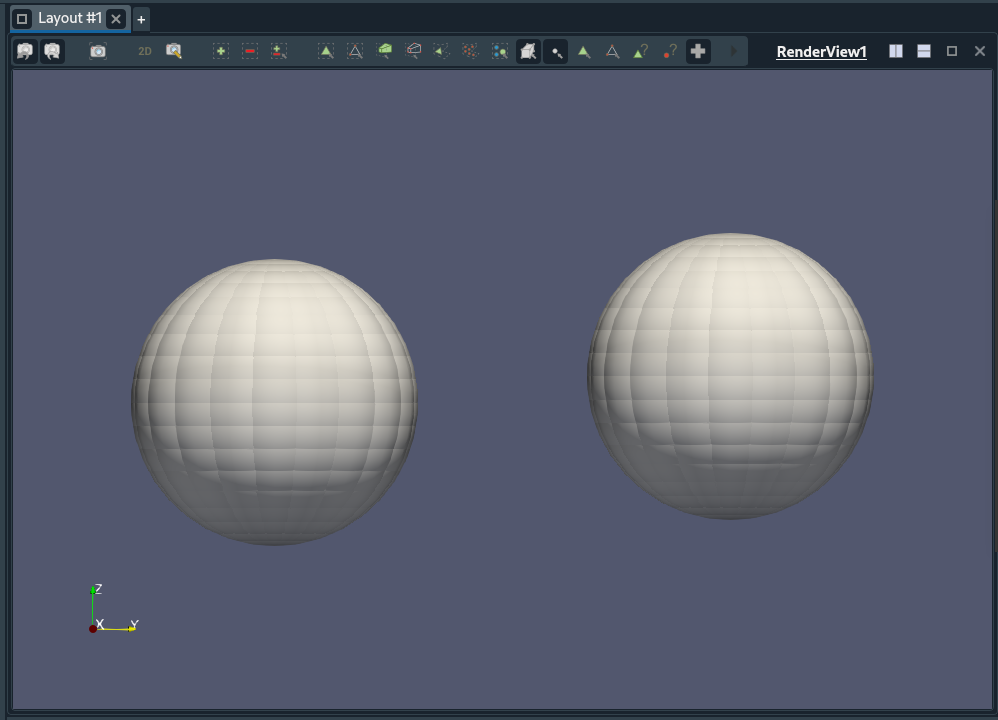
However, it was doing something weird. For the sake of understanding, could you please comment on what was happening there? i.e., applying Sphere Glyph, and changing/ introducing 3D Glyph only in Display (GeometryRepresentation) tab as: (that is by not doing ConvertToPointCould filter)
oh! But shouldn’t I first apply filter ConvertToPointCloud then?
I tried selecting it directly under Display tab, and it shows nothing.
Like in the screenshot below:
 ) was not visible. Downloading the binary directly, fixed it, among many other weird things I had.