I’m following guides online, but they fail to give me the desired results.
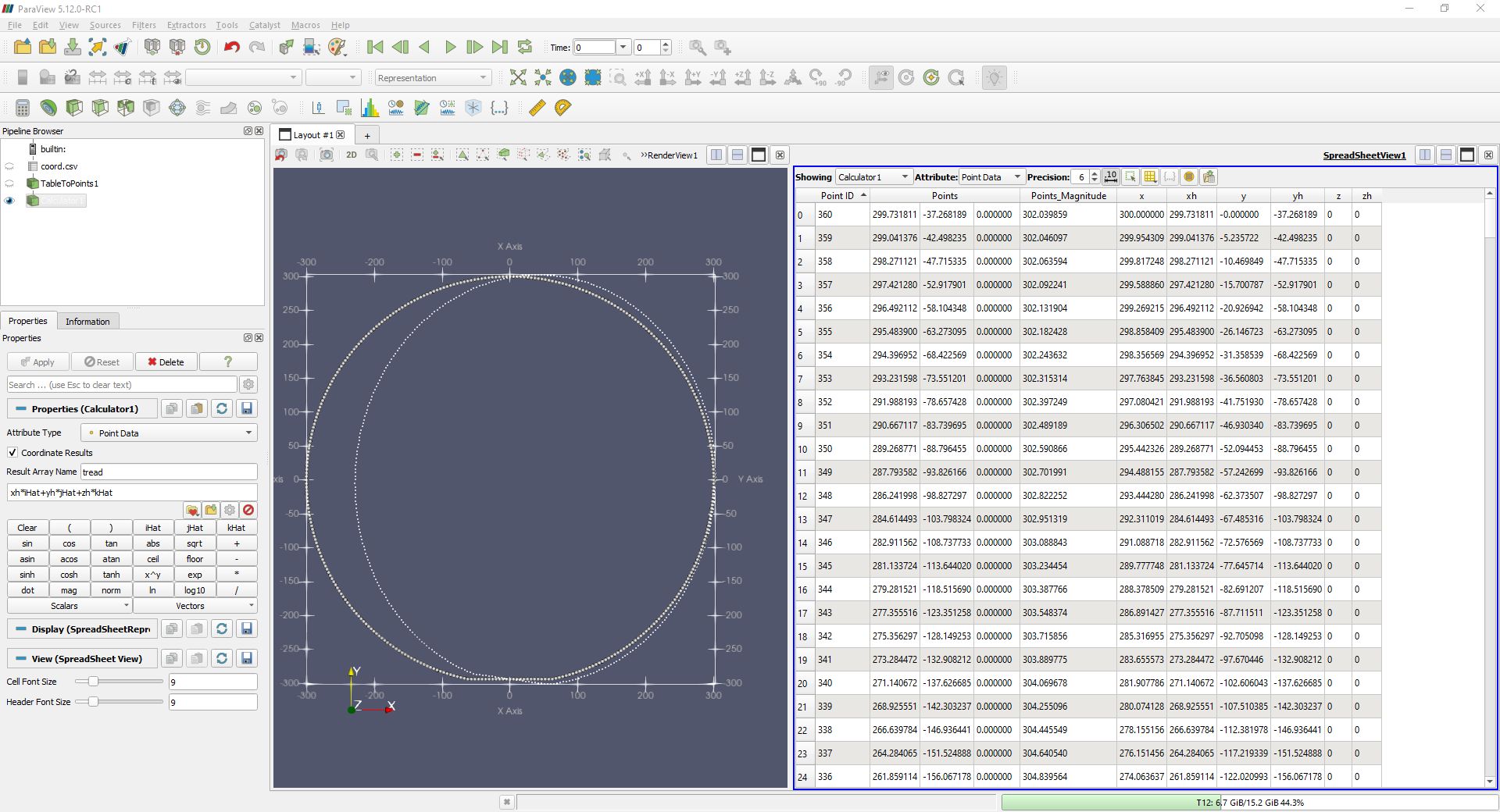
I have imported a sheet with two groups of vectors. The coordinates for the vector’s origins are [x,y,z], and the vectors are [xh,yh,zh].
So looking at my screenshot, you’ll see the circle of points on the left are the vector origins, and the circle on the right is their destinations.
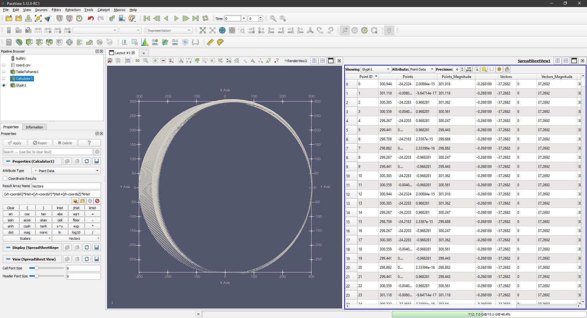
My attempts result in vectors running parallel to the x-axis and not in the desired directions.
How do I proceed to create vectors using [x,y,z] as the origin?
I will add multiple planes to the z-axis, so I’m open to suggestions as to what I should use instead of arrows.
Thank you in advance.
Hi @NeilKeith,
As you are creating a vector field,I guess you should uncheck “Coordinates Results”
Then I would try this formula (xh-x)*iHat+(yh-y)*jHat+(zh-z)*kHat to get the difference as a vector.
Hope this helps!
Thank you for your response.
If I use your formula as you’ve written it, I get an error message. However, within the scalers drop-down menu, the listed coordinates have the prefix coords; using them within your formula creates the vectors and magnitudes within the table. I’ve checked the results and can confirm the directions and magnitudes are all now correct.
The glyph arrows are now representing vectors correctly, thank you ![]()
I will now go back to my spreadsheet and generate multiple z-axes so I can produce a 3D image that would produce vectors in the thousands. What would be the recommended alternative to the arrows?
Great! Happy to read that you get the expected result.
I’m not sure to understand your goal. If you generate a Z component then switch to the 3D view, the arrows would be the correct representation.
To visualize a vector field, you may try streamlines or surface LIC. This webinar covers these techniques: Kitware ParaView Streamlines Webinar on Vimeo
This is for the sideview of a non-rigid rotating body (bike tyre).
The z-axis (zero) is the tyre’s centerline; I’ll create additional z-axes at varying degrees apart that’ll consider the change in x and y.
Hopefully I can rotate this in a 3D view so that the mapped vectors of the contact patch can be viewed in detail.
If that goes according to plan, then I’ll consider adding additional equations for turn and lean.
I’ve never created a vector before, let alone rendered one, so I’m using this an opportunity to learn about tyre vectors with the goal of visualising camber thrust.