Can ParaView draw an isosurface = 1 from the .VTK file attached? “Contour” filter fails. But “Legacy Reader” reads it correctly, and “Points Gaussian” represents it correctly (screen shot). So, I wonder if there is a workaround: a pre filter? a file reader? some other method?
Result: Correctly renders data points for 8 spheres (screen shot).
Scalar values:
0 = Blue = center of 8 spheres.
1 = Yellow = points on surface of such spheres.
2 = Red = points in the space between spheres.
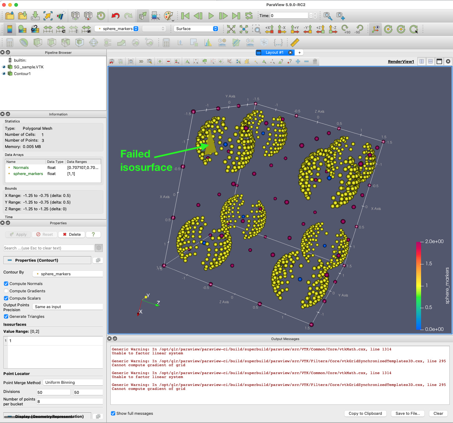
Add filter: “Contour”.
Result: Expected: Renders isosurfaces ( = 1) for 8 spheres. Observed: Renders a single triangle. Output Messages:
      Generic Warning: In /opt/glr/paraview/paraview-ci/build/superbuild/paraview/src/VTK/Common/Core/vtkMath.cxx, line 1314
      Unable to factor linear system

      Generic Warning: In /opt/glr/paraview/paraview-ci/build/superbuild/paraview/src/VTK/Filters/Core/vtkGridSynchronizedTemplates3D.cxx, line 295
      Cannot compute gradient of grid
MY SETUP:
ParaView Version 5.9.0-RC2 (The latest, Dec 10 2020, from https://www.paraview.org/download/ )
I think there are a few issues here. Lets start from the top.
File formats in many OS’s are case sensitive. If you go File/ Open/ then look at the possible extensions, you will see that .VTK is wrong, and it should be .vtk.
Next, you asked for a STRUCTURED_GRID. The dimensions X, Y and Z tell you the number of points you get in the X, Y and Z direction. For a 2,2,2, you only get 8 points, and these will be in the corners of your cube. Note that ParaView used the first 8 points you gave it for the dimentions of your weird, warped cube. (Use representation Surface). Below, I will give you an example that does work of a dimension 3,3,3.
You can’t arbitrarily read in points in STRUCTURED_GRID. That isn’t the definition of “Structured”. You probably want some type of unstructured grid.
With the mesh you have, you can then run a contour. Note, again, that you may NOT add points as you have done above.
Attached is a small, toy STRUCTURED_GRID that works, 3 3 3. sg_sample-alan.vtk (1.0 KB)
I changed my files from .VTK to .vtk to comply. Thanks for the tip.
Because Gaussian Points can read and render the file (including its extra points), I was wondering if there could be some tool (filter etc.) to convert it into an unstructured grid. If not (as it seem to be the case), I would have to bite the bullet and learn/create an unstructured grid myself as you suggest. In that case, are there any toy examples of an unstructured grid that might work?