Hi forum,
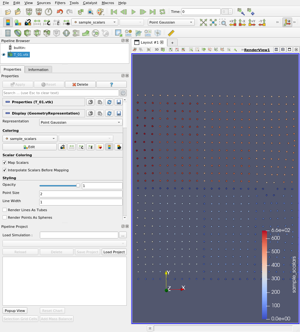
I created a text-file as described in “File Formats for VTK Version 4.2” for viewing the streamline. But something went wrong. The Informations are shown, but I can not create the streamline. Is there somebody who can take a look on my file? Thanks in advance.T_01.vtk (40.9 KB)
Dear Mathieu,
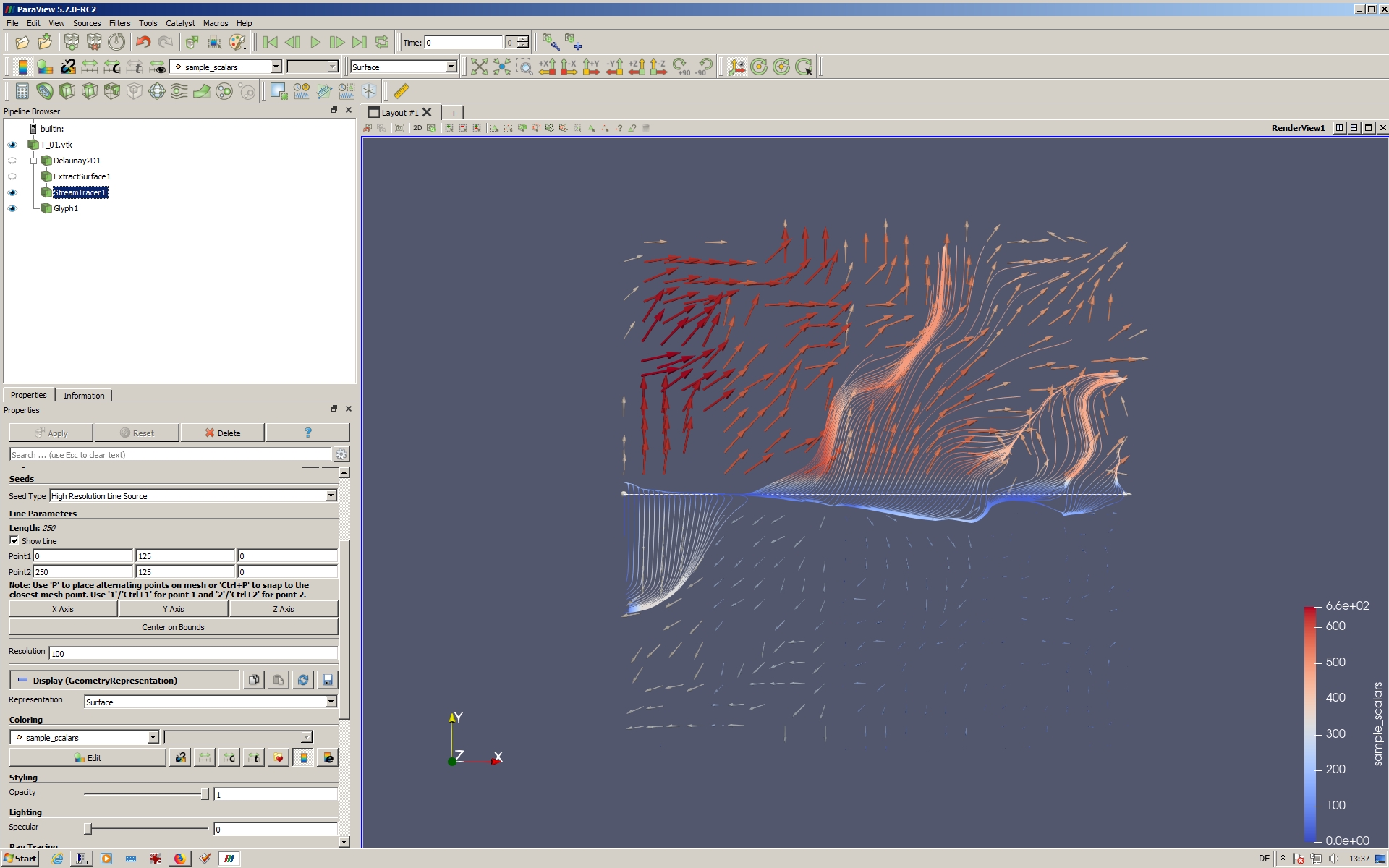
Thnaks for your request. Of course, I applied a Delaunay2D- and an ExtractSurface-filter. But now starts the problem. See the picture posted. The streamline has not much correspondence to the vectors(Glyphs). Probably I made some where a mistake, but dont know where.
Harald
The streamlines look like they are following the glyphs of the vector field to me. I’m not sure what you mean by “not much correspondence.”
Perhaps what is confusing is that your vector field seems to have a divergence right where you are putting the line. That is, the vectors seem to be pointing away from the line in both directions. But the streamline filter does not know that. It just looks at exactly where the line is to see which way the vectors are going. Sometimes they are going up and sometimes they are going down.
I suggest adding two streamline filters to your data. One with the seed line moved up and one with the seed line moved down.
Hi Kenneth,
Thanks for your suggestion - the further streamlines kompleted the surface. But I saw that every new streamline filles only a part of the surface. So probably when using more steamlines the surface will be filled completely. Is that so?
By the way: can you recommand some literature about how the streamline works?
have a nice day.

The Wikipedia article on streamlines is as detailed an introduction as any other I know of, but here is the idea of streamlines in a nutshell:
You take a weightless particle and move it around by the vector field. That is, the vector at the particles location determines its exact speed and direction. As the particle gets pushed through space, we trace the path that the particle travels.
That description is not very mathematically precise (which is why you’ll often hear it defined in other terms), but I think it is a fairly intuitive way to think of it. In the case of the ParaView filter you are using, the filter takes a particle that starts on the line you put in space and then traces that particle has the vector field moves it around. (It also traces it backward to find its origin as well.) It does this for 50 particles spaced evenly across that line defined in space.
Thus, if the streamlines are not covering a part of your data, that means that none of the particles traveled to that region of space. That might mean that the flow is simply not going into that area. (Keep in mind, though, the where you place the seed points will dramatically affect what streamlines get generated.)
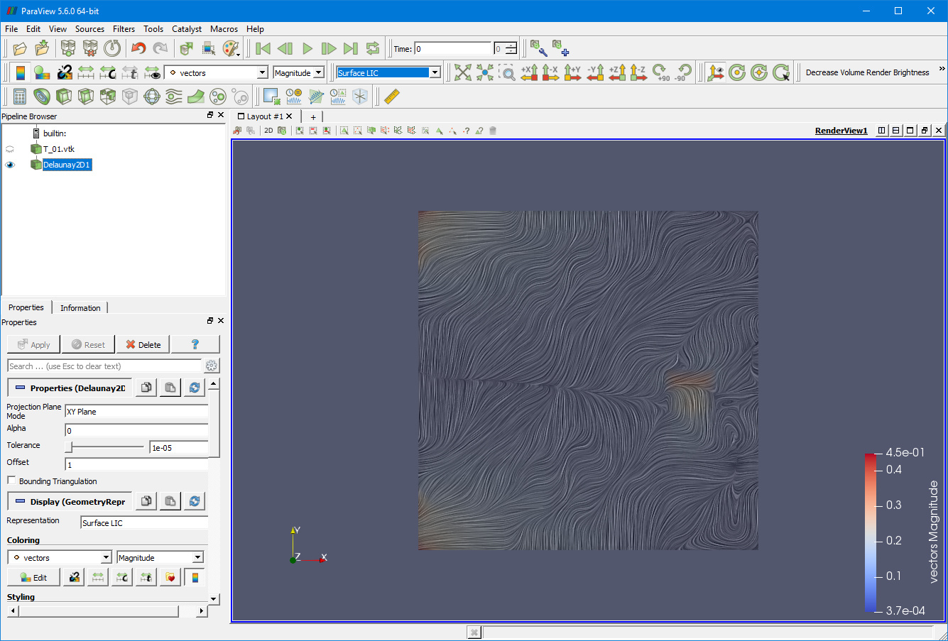
If you really want to see the stream everywhere, you may be looking for a visualization technique called Line Integral Convolution or LIC for short. This will densely draw draw lines everywhere on a surface. ParaView contains a plugin that can draw LIC surfaces. To enable it, go to Tools -> Manage Plugins. Then select the SurfaceLIC plugin and click Load Selected. Once it is loaded Close the plugin manager and then go back to your data. Turn on the visibility of your Delaunay 2D filter and change the representation (combo box in the middle of the second toolbar) to Surface LIC. Here is a capture of what that would look like.
Hi Kenneth,
This is exactly what I’m looking for. I did not know LIC, but it seems to be the solution for my problem.
Thank you for your help.
Have a nice day.
just like this.
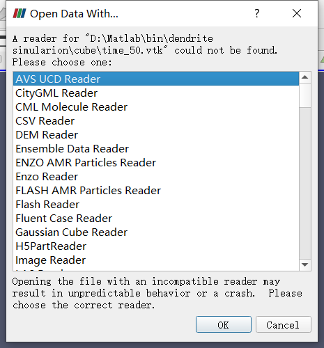
does it mean the file is invalid?
You .vtk file seems invalid. But open your own topic please.