I agree with @mwestphal that the best solution for this problem is to have your code identify which cells are part of the additional boundary cells and which are supposed to be the original mesh.
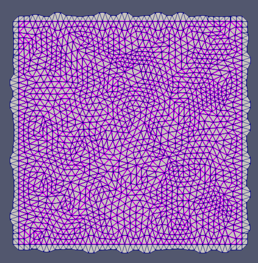
To elaborate a bit, this idea of having 1 or more layers of boundary cells is very common in parallel simulations and visualizations so that you can get information about data in cells in neighboring MPI processes without having to do lots of communication. These “boundary” cells are called ghost cells (or sometimes halo cells) because although you represent them as part of your mesh, they are not actually part of your mesh. When rendering the visualization, you want these ghost cells to be removed, which is the same situation you have.
Ghost cells are identified using a cell field. All cells part of the actual mesh would have a value of 0. All cells part of the boundary layer would have a value of 1. If you are writing out your data into a VTK file format (like .vtu), I think you just need to name this field vtkGhostType and ParaView will pick it up as the ghost cells and automatically remove the boundary cells.
Even if you can’t get ParaView to pick up your cell field as the ghost levels, once you have it you can easily remove the boundary layer using the Threshold filter.
Like I said, I think this is the best solution to your problem. It is a common solution for a great many solvers, and if you can modify your simulation code to write one out, your problem will be solved. If, however, it is not practical for you to make this change in the simulation code, here are some less great solutions.
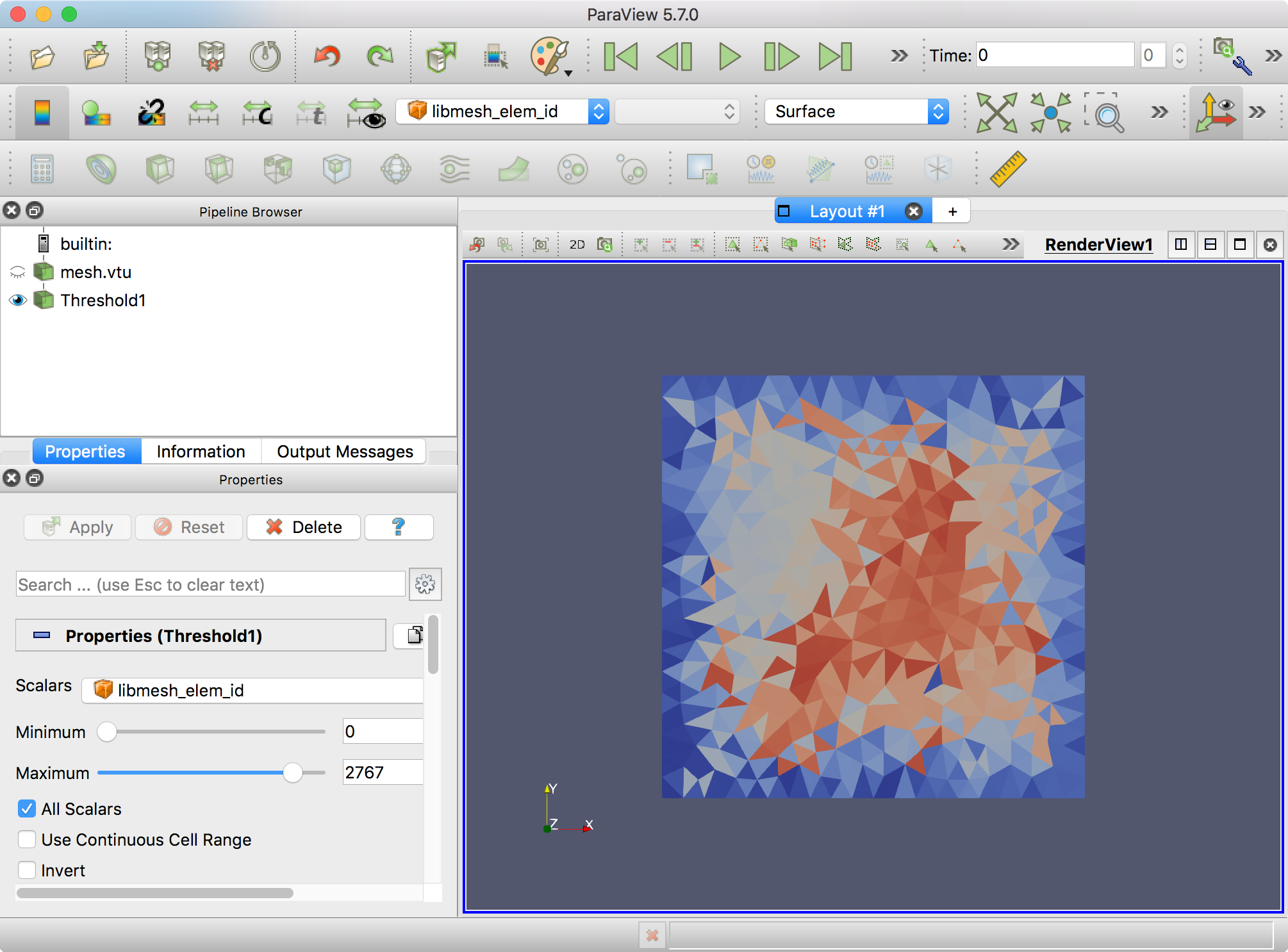
I note that your data has a field named libmesh_elem_id, which appears to give a unique identifier for each cell. (You can actually create an equivalent cell field with the Generate Ids filter.) I further note that all the cells in the boundary layer have a higher id than those in the actual mesh. For example, in the data you posted I note that the cells of the actual mesh have libmesh_elem_id values from 0 to 2767 and that all the cells on the boundary have values from 2768 to 3097. Thus, you can use the Threshold filter to pull out all cells with libmesh_elem_id between 0 and 2767.
Of course, this will break down if the number of cells in your mesh changes. You would have to adjust the threshold values, so not a great solution.
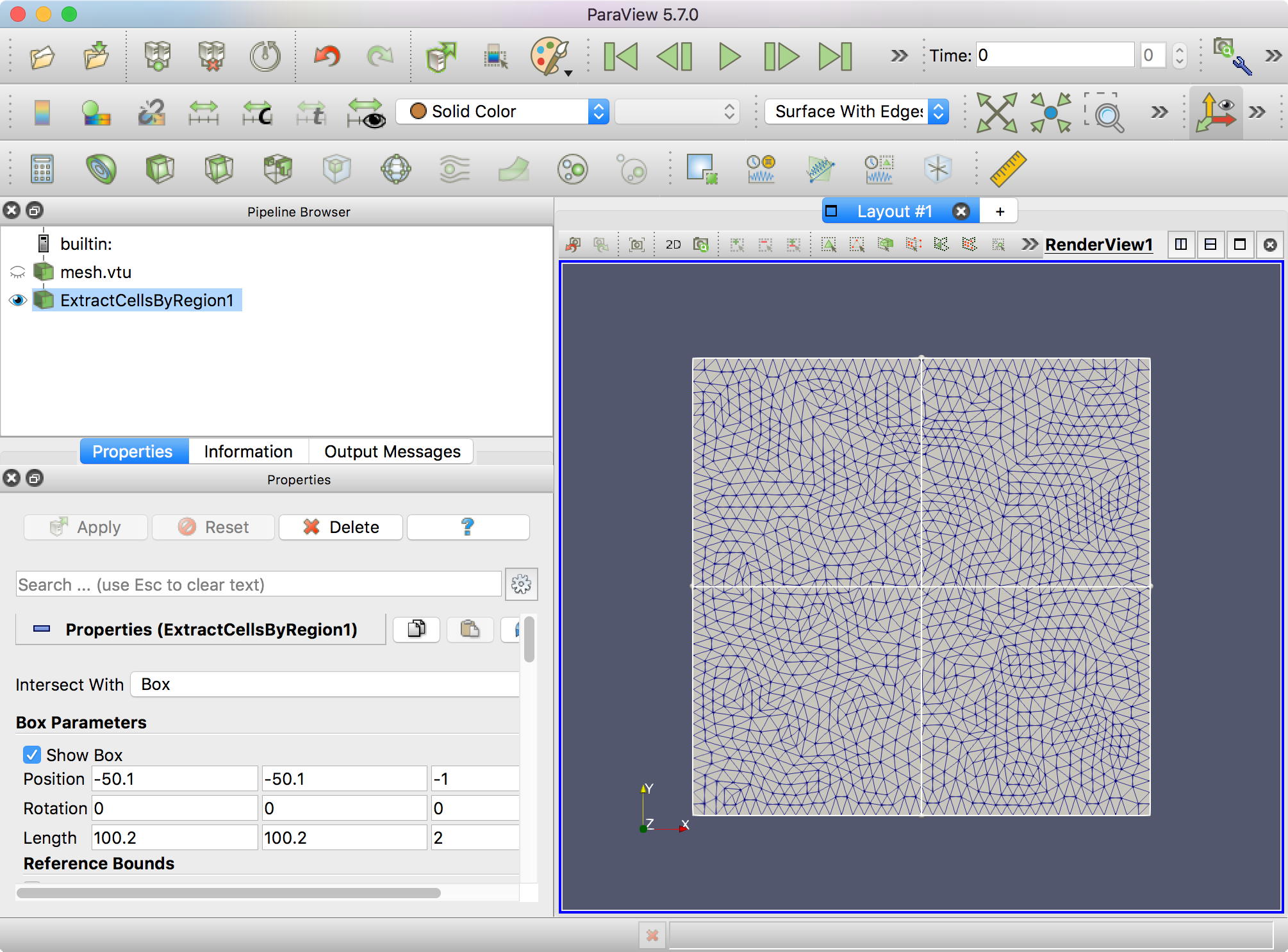
I also note that the actual cells in your mesh fit in the physical space between -50 and 50 in the X and Y direction. Assuming your mesh is always within this physical range, you can use the Extract Cells By Region filter to pull out only the cells in the physical region. To do this, make sure you Intersect With a Box. Then set the box to be a little outside this boundary.
Once again, this approach will break down if your mesh changes. If your mesh moves out of this physical space, then you will no longer be extracting the exact right cells. So again, not a great solution.