I maintain a code that performs diffusion and chemistry simulations on an unstructured mesh. Calculations are performed on objects that have a surface mesh and an interior mesh. Meshes are based on 3D Voronoi tessellations. Each mesh point “owns” a volume that corresponds to its Voronoi cell. The surface of the object is defined by a triangulation on the set of surface points. My code can perform its own rendering, including cross sections that reveal the interior. Example rendering, performed on a spherical-shell-shaped object:
I’d like to add to my code the ability to spit out some kind of data file that can be read and rendered by ParaView in order to take advantage of ParaView’s much more flexible rendering capabilities.
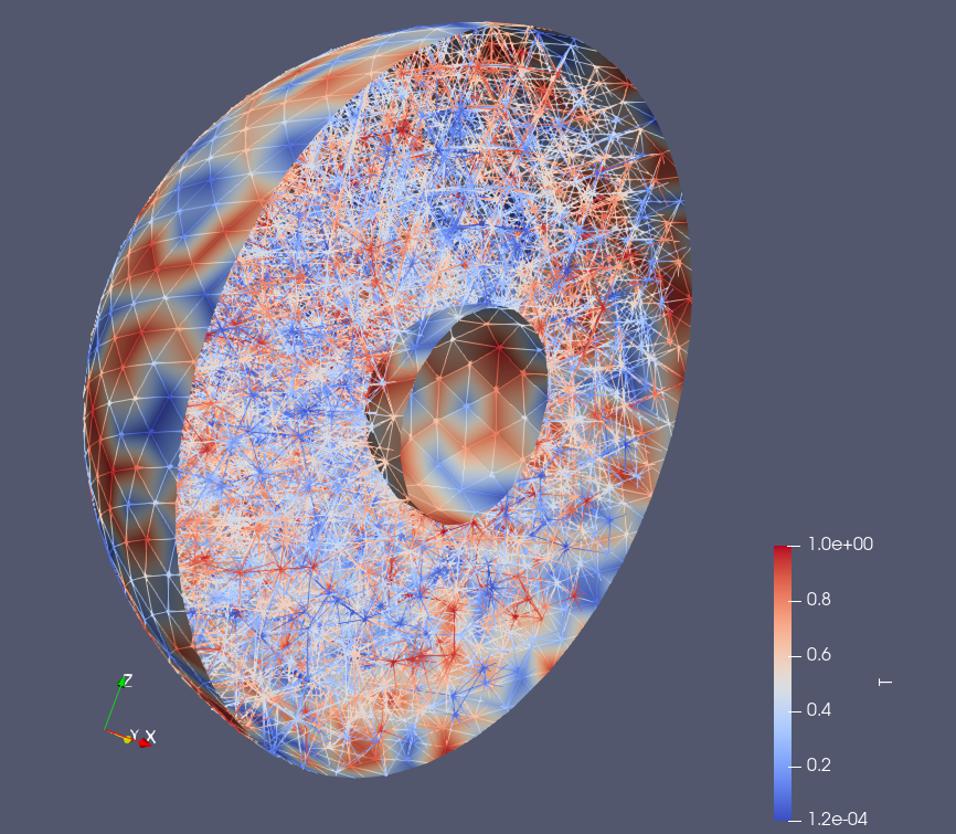
I am brand-new to ParaView. I downloaded it for the first time a couple of weeks ago and have been fiddling with it, but I can’t figure out how to render an image like the one above. I’ve consulted all the tutorials and guides I can find, and I can’t see anything that matches. Furthermore, I’m not really familiar with any of the data formats that ParaView supports. I managed to figure out what a vtk file is, and I wrote a widget into my code that writes a vtk file describing the surface polygons (triangles), points, and “lines” (Voronoi neighbor relationships between points). I can load this into ParaView, invoke “clip”, and create the image below:
How can I get ParaView to render the cross-section plane of the interior revealed by the clip operation? What kind of data file format should I have my code spit out, and what information should it contain? What ParaView options should I invoke to get an image that is roughly similar to the top image above created by my code? It doesn’t have to be exactly the same. For instance, if it interpolated the interior slice somehow instead of using the nearest-neighbor color, that would be fine.
Here is the vtk file my code spit out and which I’ve used to generate the ParaView render above:
The data you are creating is a vtkPolyData, and it only contains the triangles and lines. So that is what ParaView is rendering and clipping: triangles and lines. If you want ParaView to clip your data as a solid, you have to provide data that is solid. That is, you need to provide ParaView with polyhedra, not polygons and lines.
You need to write out a VTK file that contains an UNSTRUCTRED_GRID, not a POLYDATA. The unstructured grid should be a collection of polyhedra, each of which represents a cell in your Voronoi tessellation. Although not well documented, I believe that you can write out the cells as a “convex point set”. This allows you to define a cell with a small set of points, and the cell will be the convex hull of those points. This is cell type 41, so when writing out the cells, identify the cell with type 41.
“That is, you need to provide ParaView with polyhedra, not polygons and lines.”
I understand what you’re saying, but my code as currently written doesn’t actually store the data required to provide that information. It would require a great deal of re-writing of code to make it work. I just want to check a few things before I take that step.
I just discovered that ParaView can almost do what I’m describing. If I invoke the Delaunay3D filter, I get the image below:
It has successfully built a Delaunay triangulation around the set of points defining my mesh, but it doesn’t know about the hollow center. Is there some way to get ParaView to “clip” a triangulation at a closed surface defined by polygons? So that the Delaunay tetrahedra would stop at the surface?
Also: Is there some other file format besides VTK that might be better for my purposes? I don’t know, VTK was just the first one I tried.
Unfortunately, there is no way to clip the geometry based on a mesh surface.
If your mesh always has this simple shape, you can get rid of the middle by doing a second clip and changing Clip Type to Sphere. You need to set the center and radius of the sphere correctly, and you want to uncheck Invert.
Unfortunately, that simple shape was just an example. The mesh could have any kind of complicated shape depending on the problem. So I guess the simplest way to do this is to make a VTK file with something like a list of Delaunay tetrahedra in it.
One last ditch attempt: Can ParaView infer a set of Delaunay tetrahedra from a list of vertex connections or edges? In other words, suppose you have a list of vertices and a set of edges specified by information like “Vertex 1 is connected to vertex 7, Vertex 2 is connected to vertex 11, etc,” but you don’t directly have information about tetrahedra in the form of information like “Tetrahedron 1 is made of vertices 2, 3, 7, 9; Tetrahedron 2 is made of vertices 11, 6, 25, 1; etc.” Can ParaView “fill in” the missing info in that case?