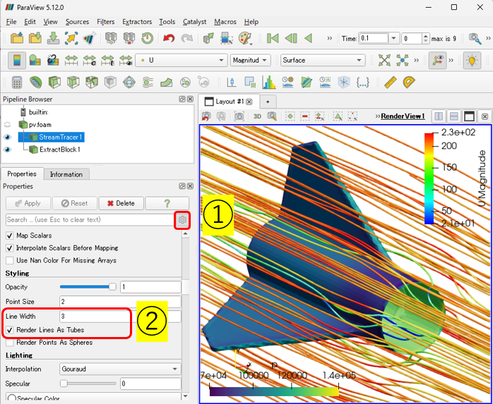
I noticed that under the properties for the point cloud stream tracer that i only have U available as the vector in the drop down, nothing else is listed. How do i view the other vectors and increase the tracer size to be a little thicker?
this is what paraview shows i have. I should have more than just “U” because when i change the type from the drop down, the rocket fin changes with respect to whatever i pick
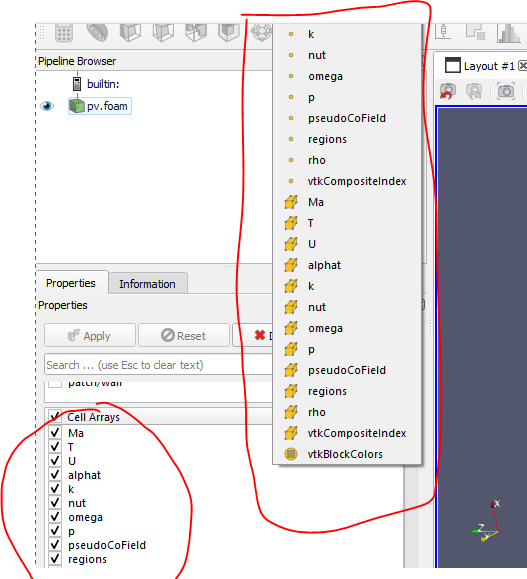
“Does your data include vector quantities other than U (flow velocity)?” how do i verify this and how do i make sure others are added? I thought they were added since the cfdof workbench showed the plot of all the residuals, not just U
The stream tracer is applied to vector variables. Therefore, if ‘U’ is the only option available from the drop-down list, it implies that ‘U’ is the vector variable, while the others are likely scalar variables. You can also verify whether a variable is vectorial by looking into the Information tab, which presents the maximum and minimum values of each component for the variables.
The calculation of Cp, Cd, etc. must be performed according to the defined procedures, some of which can be found on YouTube you have previously mentioned and other websites.
However, to consider the impact of viscous forces in drag force calculations, wall shear stresses are necessary. It appears that calculating the velocity gradient tensor near the wall surface, which is essential for this purpose, in ParaView may not yield sufficiently accurate results. Therefore, I recommend performing Cp, Cd, etc. calculations within OpenFOAM for greater accuracy.
I am not sure exactly how to do that. I don’t use the command line for open foam. I use the workbench in free CAD.
So I’m not entirely sure how to accomplish that. But what’s going on with the current data that I have that makes it difficult to calculate the coefficient of pressure and drag?
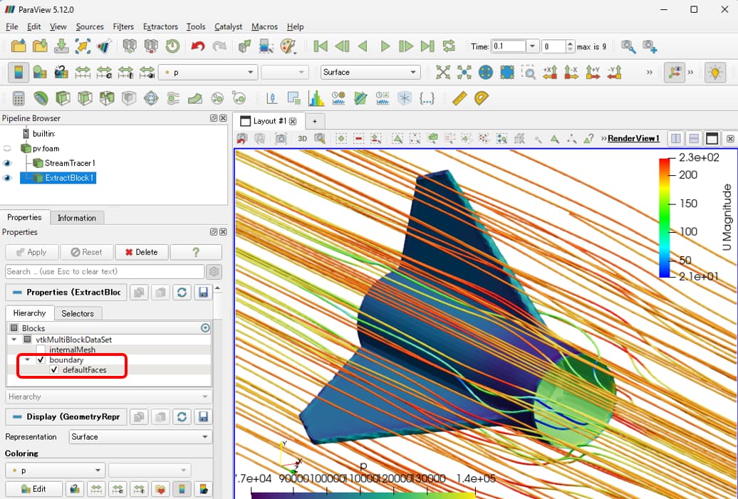
I believe the pressure coefficient (Cp) can be calculated by applying a Calculator filter to defaultFaces , as outlined in the following documentation: OpenFOAM: User Guide: pressure
For the drag coefficient (Cd) of defaultFaces, the proposed procedure is:
Calculate the Wall Shear Stress (WSS) (search within this discourse for the method).
Compute the drag force using the method described in the aforementioned YouTube video, where the product of the normal vector and static pressure is calculated for each element. It remains uncertain whether the element area should also be included in the calculation.
Manually calculate the Cd based on its definition.
ok, cool. ill look into it. I think one of my issues is in the CFD OpenFOAM workbench of freecad, i picked high mach number for the physics model and DES as the turbulance type. I think this triggered the workbench to use the HISA solver rather than simplefoam.
I am only guessing because in the D:/CFDDUMP/case/0 pressure file, the dimensions are:
[0,-2,-2,0,0,0]
meaning time would have to be an exponent in the denominator since we cant travel back in time.
using the filter in paraview called integrate varibles i think is causing issues since integrating my not be the right step.
Do you know how to switch between simplefoam and hisa in the CFDOF workbench? or is it automatically trigged based on settings i pick?
It’s okay it’s a workbench and free CAD that is a UI for open foam. But I’m guessing anytime I use a higher Mach number and compressible flow that it triggers open foam to use the high speed aerodynamic solver rather than simple foam. So I have to figure out how to make open foam compute all my Force coefficients for me rather than having paraview because integration won’t work with the high-speed aerodynamic solver cuz of the way it handles the pressures. It uses real pressure instead of a normalized pressure
Guys Help me, I think I’ve got same problem with stream tracer.
The path line can’t see. Please somebody check my file, thanks kindly for your reply guys… Flow Test 1_0_0.vtu (1.2 MB)
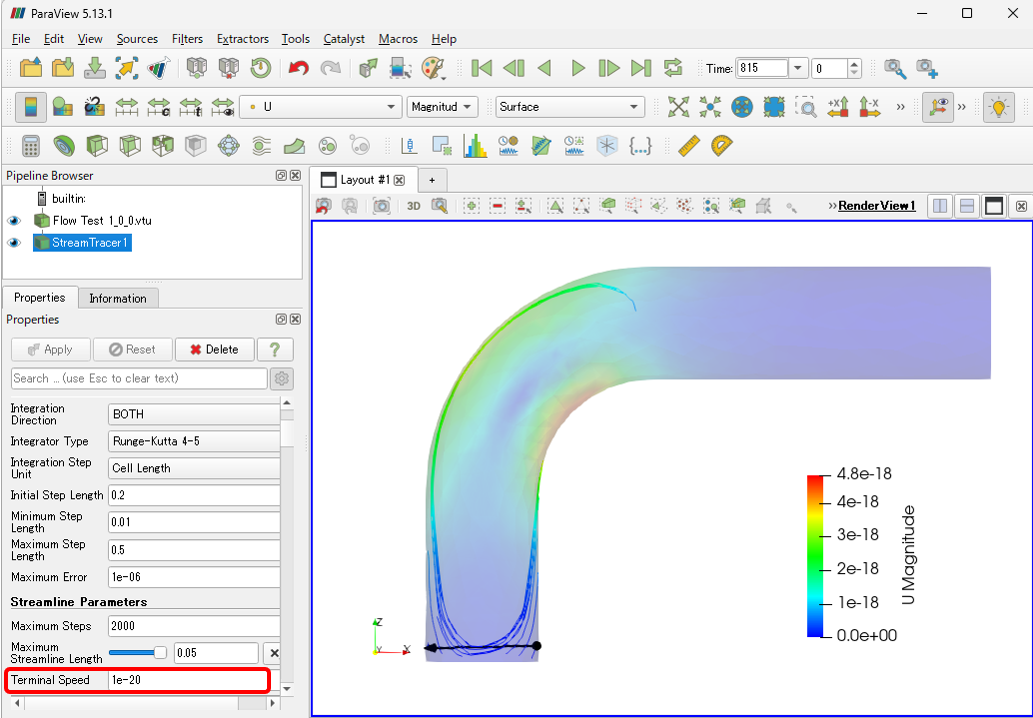
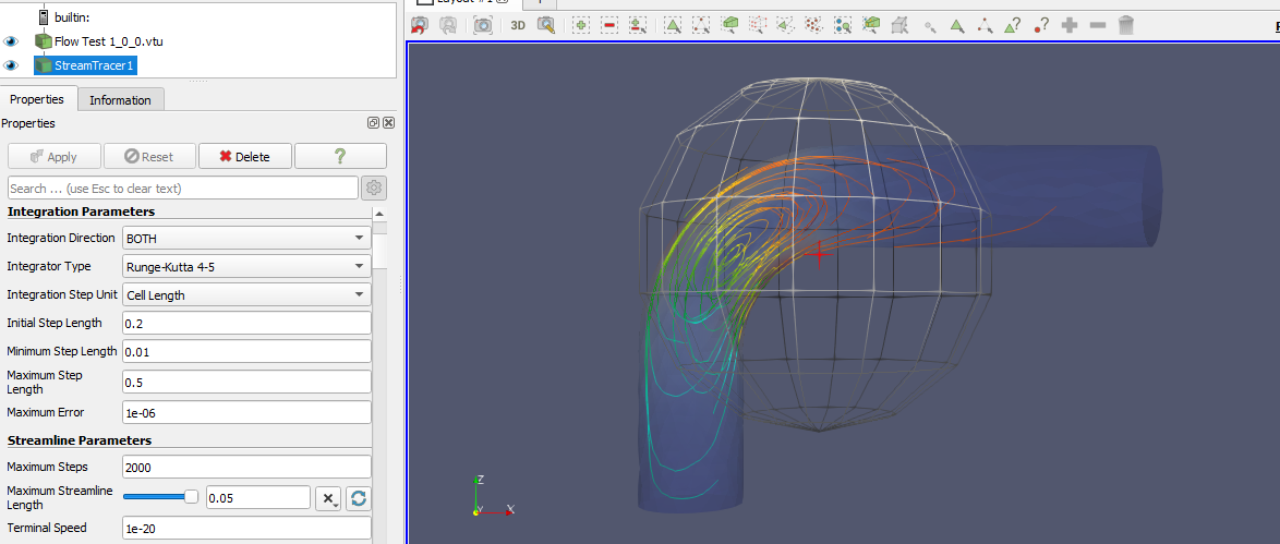
I checked your data and found that the value of the variable U is almost zero, indicating that no flow field exists. This is likely the reason why you are unable to draw streamlines.
To draw streamlines, you need to use data where a flow field is present or set the Terminal Speed in the Streamline Parameters to a very small value.
Arigatō @Kenichiro-Yoshimi, I’m not realizes that setting and I’ve upgrade my Paraview to last version (before I use 5.10 there’s no terminal speed setting)