Surface Flow filter gives a wrong value

Hello everyone,
I looked around the forum and found no other report of this so I create a new topic. I am currently analyzing a biphasic case (air-water) of a buried river flowing under a city. The calculation was done with Ansys CFX. I had a lot of repetitive analysis to perform on the data and CFD Post was really slow so I exported my results to CGNS and managed to analyse them with paraview which led to two conclusions:

  • Paraview is so quick to analyse it amazes me and so versatile in the same time with the python console! anyway this is obviously not my problem
  • Surface flow filter is giving me underestimations of flows whereas CFDPost does not

So I tried it the old way by calculating the projection of my velocities on the surface normal and using the integratevariable filter. The result was the same as the Surface flow, which is coherent but not better.

The error is correlated to the total area of the surface : the bigger the surface, the closer the results so for me the Paraview treatment of the velocities value on the perimeter is wrong

But I may have done something wrong myself, even if I can’t see why yet!

regards,
Thomas
So you think the error is in the Integrate Variable filter ?
What makes you think the results is an underestimation ?
Do you know how CFDPost makes the computation ?

Ideally, we would need a dataset were the computation can be done by hand and which would shows that ParaView underestimate the results.

Hi Mathieu,
thank you for your reply,
I should have written that I impose 33 m3/s on one boundary and I calculated the flow in a section of the same tunnel where nothing happens to the flow yet, so the flowrate must be 33 m3/s. CFD Post gives me 32,9 m3/s which is ok and Paraview gives me 30.2m3/s, which is 8% inferior to the expected value.

I do not know how CFDPost does the calculation but I have used it a lot in the past years and I never found a noticeable issue regarding mass conservation (when correctly converged) so I am pretty confident in the result of the software

Regards,
Thomas

Could you share a simple dataset that shows this behavior ?

Ok, I will extract a dataset by tomorrow,
regards,
Thomas

Hi again Mathieu,
here is a dataset in PVD that shows the behaviour, steps to reproduce :

-Paraview v 5.5.2 (portable version, no admin right for me :https://www.01net.com/telecharger/windows/Multimedia/cao_et_dao/fiches/144490.html)

  • create a Slice of type plane, ORIGIN : 30.9,-208.3,5.56
    NORMAL : 0.28, -0.96, -0.0137
  • apply a Surface flow filter, input variable is “eau.Velocity”
  • result is 30.4854 (m3/s), in CFDPost at the same location it is 32.9844 m3/s
    SC1_dataset.zip (2.0 MB)
    regards,Thomas

Hi everyone,
Did you have a look at my dataset ?
do you have any clue about this behaviour?
Thank you
Thomas

Sorry, I had no time to look into it yet.

up. Right now, the only reason I and the CFD team here in my office do not switch to paraview is because of that issue which lead to no confidence in the integrate filter. I do not think this is a big issue but the difference is there, I would really apreciate some hints.
thank you

I have almost the same results as you, 30.5249, but to check and fix the issue would require some time.

1 Like

Any news on this topic? I have a similar problem computing the mass flow rate.

A simple question. Does Surfuce flow filter use the same routing of Integrate variables?

Hi,

I believe the surface flow filter will always deliver wrong results.

My setup was a pipe of 400 mm with water flow of 1,71 m/s, gives 775 m3/h.
A slice through the pipe and using surface flow gives: 569 m3/h (73%).

The Paraview docs says the following about SurfaceFlow: “The flow integration filter integrates the dot product of a point flow vector field and surface normal. It computes the net flow across the 2D surface…”.

So it integrates the point data of the slice, not the cell data.
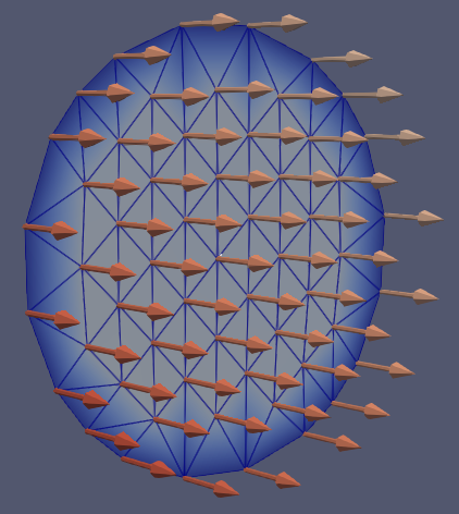
Below is the slice showing the SurfaceVectors (U, perpendicular). All the vectors at the edge of the pipe have zero velocity (requirement for CFD with non-slip wall). About 45% of all points are on the edge, so roughly half of all point values will give zero to the integration.

image

With turbulent flow, the edge is only a minute area of the total pipe. Still, if the resolution is not very high, using SurfaceFlow, this will seriously affect the integrated flow.

A more accurate approach according to me is:

  • generate surface with a Slice;
  • calculate for each cell (not points): desired flow perpendicular to the surface;
  • then IntegrateVariables, and check the spreadsheet for integration of the perpendicular flow.

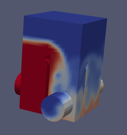
My setup was a splitterbox with incoming pipe (left), a weir, then a division for 30/70% flow split and two outgoing pipes, all pipes 400 mm diameter, see figure below.

image

This is a two phase flow (water/air) and the velocity vectors give the velocity of the cell, which can contain a mixture of water and air (alpha = water fraction).
So to get the velocity of water at each cell in the pipes, my calculation was: alpha x Ux or alpha x Uy, with alpha the water fraction and Ux/Uy the velocity component perpendicular to the section of pipe.

Results, for last time frame (after 60 s):

  • flow in: 754 m3/h (97% of true value of 775 m3/h);
  • flow out 30%: 242 m3/h (32% of in);
  • flow out 70%: 536 m3/h (71% of in).

Not bad for an overcharged splitter, at one point in time, with low resolution (13000 cells).

Therefore, to remedy the problem with SurfaceFlow:
I would suggest to integrate the dot product of a cell flow vector field with the surface normal.
This will solve the issue with the zero velocity at the edge having too large an impact on the overall integration.

1 Like