I have a triangular mesh that I visualize in ParaView. Each cell has vector data I would like to show (wind direction). I assign the cell the vector via
_vtk_unstructuredGrid->GetCellData()->AddArray(vector_dir_array);.
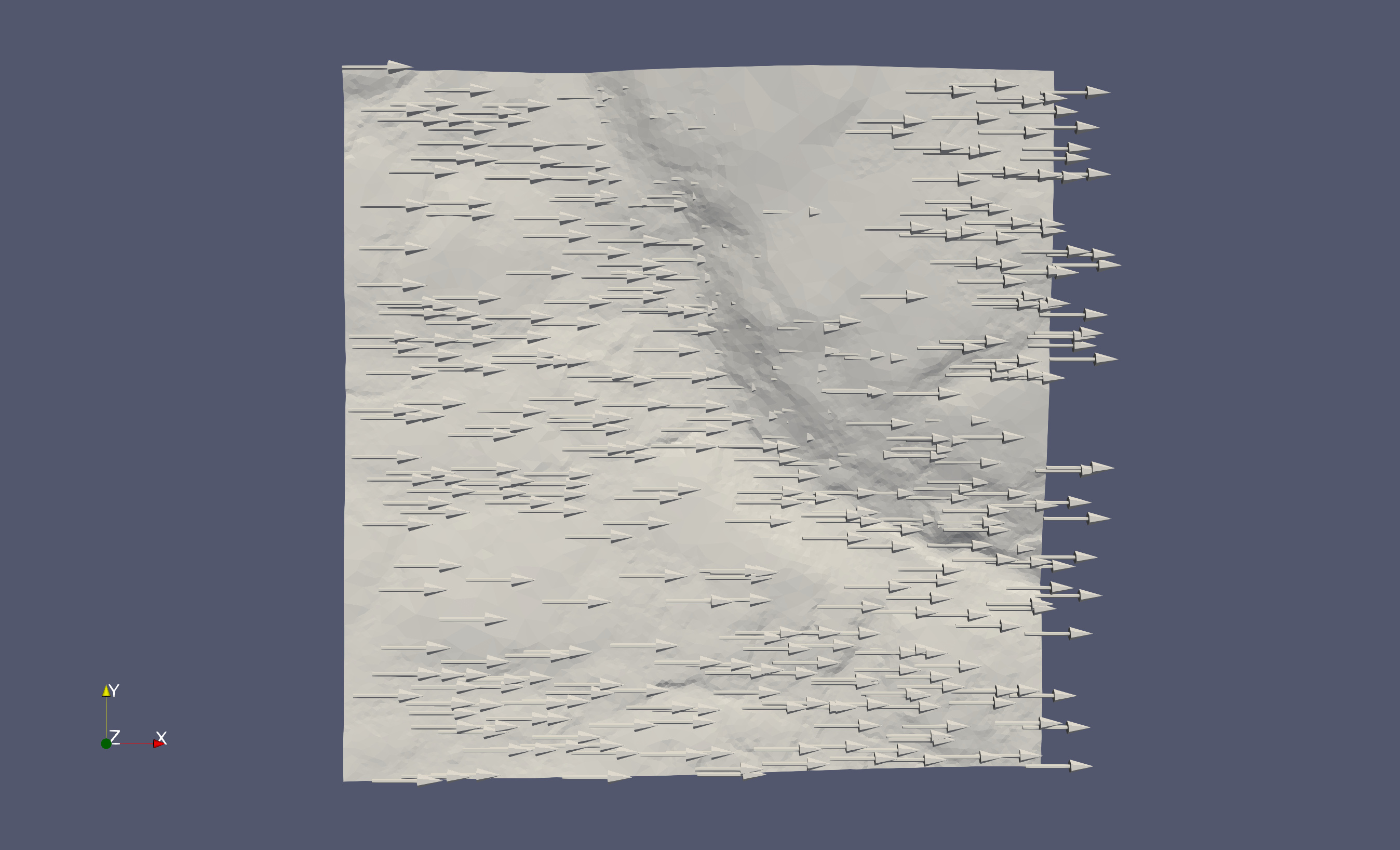
I’ve confirmed the x,y vector components are correct by plotting in Maple. When I visualize the vector via the Arrow Glyph in ParaView, and selecting the ‘Orient’ option, the glyphs are all aligned to point towards +X direction.
With just the unstructured surface displayed, if I set the face colouring to be my vector, I can choose the X and Y components separately and this shows the faces do have X,Y values that a) are different and b) don’t point in +X direction.
Would appreciate any suggestions on how to proceed.
Update: appears to be a problem with paraview 5.5.1 on MacOS. The code for the vector IO had been working previously, but I made some changes and thought I’d broken it, and wanted to pose the question w/o the overhead of “this used to work”.
On my desktop I have an old version of paraview, 5.3 RC3. However, it correctly displays the vectors, and allows for me to color them, etc.
The version of PV on my laptop is 5.5.1, and it does not correctly display the vectors nor allows for me to colour them.
@utkarsh.ayachit sorry for the slow reply, I was expecting an email if someone replied!
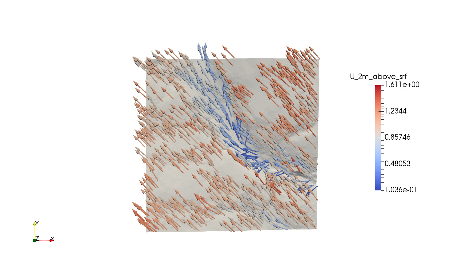
I think it’s a different timestamp than what I showed above, but the winds are from mostly the south (North is up) and they’re spatially variable, so they shouldn’t show a uniform from the west wind, like that shown in the bottom image.
I’ve confirmed this is still a problem with 5.5.1 on MacOS
Ok, -dr fixed it! That is strange… Any idea what could have happen to cause that?
Also strange: Opening the save state would correctly show the vectors, but would still fail when I tried it until the -dr command.
It is disabling loading configuration files that restore previous settings. Setting PV_SETTINGS_DEBUG environment variable will print out info on the terminal about files it loads during startup. Sometimes the crud that collects between versions can cause issues.
Gotcha. Quickly took a look at the -dr.ini file versus the non -dr one, as well as the main json config file. Nothing obviously broken. I removed all the config files and it’s correctly working. Thanks very much for the help
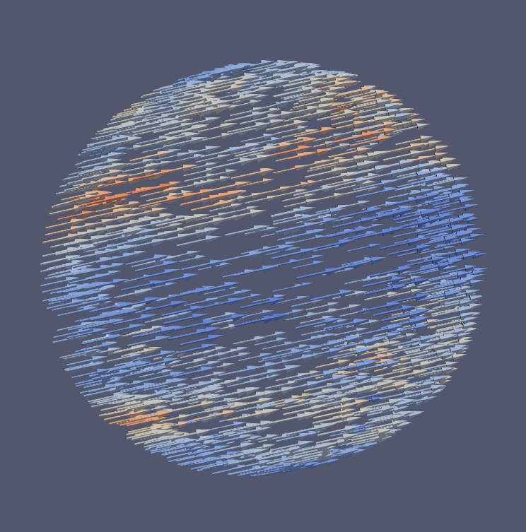
Hi I’m new to paraview and mostly have my data stored in netCDF. I’ve had reasonable success generating plots on the sphere, and are aiming to generate wind vectors (via glyphs) at different pressure levels. I’ve followed a note:
closely as it is exactly what I am trying to do.
This is currently what I see. The arrows point in the same direction, there should be changes in x/y direction.
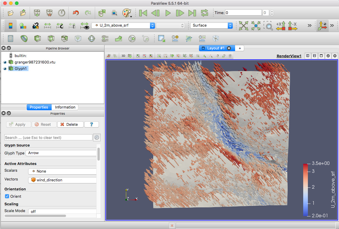
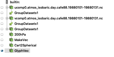
My pipeline is:
As my variables in two different files, I group them together with the filter. This seems to work as the variables (ucomp/vcomp) are both available to me.
So the 200hPa selects out a single level (200hPa).
The MakeVec follows the notes in the document above. This seems to work as ucomp and vcomp can both be plotted, they show up on a rectangular grid.
Cart2Spherical puts the component on the sphere. Once again it allows me to choose b/w ucomp/vcomp.
Then I try to glyph the result following the notes, and I get the figure above.
Any help would be great.
is this something I set prior to applying the standard glyph filter to my Cart2Spherical filter as the drop down menu for Orientation Array has no option and says “No orientation array”? I have ucomp (partial) and vcomp (partial) available, shouldn’t the option to plot the glyphs come from these objects, I can see them in the Coloring drop down menu? Not sure what the (partial) refers to. Thanks
Hello, I’m new to Paraview and I’m having the same problem: glyphs are all X-oriented even if I selected an orientation vector.
Could you tell me how do I run with the -dr dommand? Is it something you can do in the Python shell?