Could someone recommend a file format for transient result files from a CFD solver to read and analyze in ParaView?
So far, I have been using ensight gold file format to get the data from my fluid simulations into ParaView. Part of the reason why I used it is because that’s what the was used in the group back when I joined. And to be honest, I stuck with it because I actually understood the documentation. But I feel like I am beginning to push its limits. Using it with an MPI parallel solver is not exactly straightforward. And unless I messed something up with my file exports, I might have surpassed an element count limit, at least with file import in ParaView.
Here is what I need from the file format:
- easy to understand for a part-time, self-taught programmer like myself
- decent support in ParaView (obviously)
- at least scalar and 3D vector quantities, symmetric tensors would be nice to have. Results are usually defined at cell centers, but an option for vertex-based values seems to come in handy on occasion.
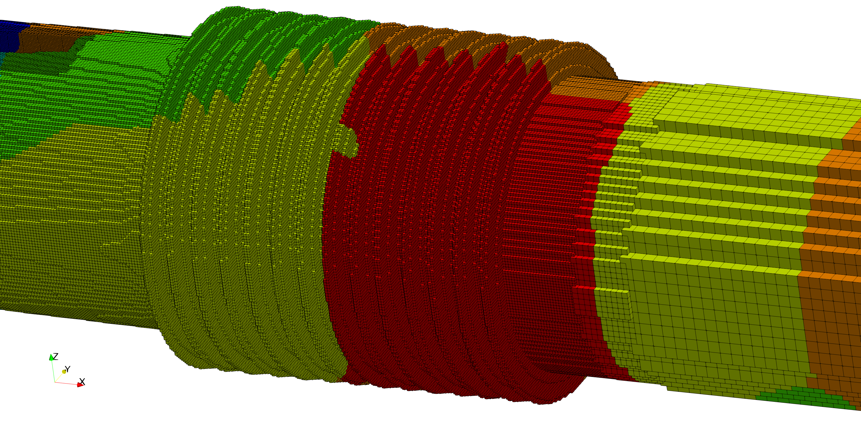
- mesh elements/cells are exclusively Cartesian cubes, or axis-aligned cubes if that makes it any clearer. However, the mesh itself is not Cartesian in the strictest sense of the word. The geometry is usually sparsely filled, and there are different cell sizes (I call it “levels”) in each mesh, with a 2:1 cell size ratio between different levels. So if there is a simple-to-use element type for this application, I would be over the moon.
- The solvers writing the result files are MPI-parallel with domain decomposition. So parallel I/O seems to be a must-have.
- The geometry is mostly stationary, while the values vary between time steps. This is one constraint that kept me from looking further into VTK. From what I understood, VTK does require writing the geometry for each time step in transient cases, even if it does not change.
- Part of the mesh must be able to move. We haven’t implemented moving meshes yet, but will start with it quite soon. There is no deformation, the cubes retain their shape. But they translate and rotate between time steps. Total cell count remains constant.
- Speaking of cell count: I am currently having trouble with ~400 million cells. Sooner or later, we will have cases with more than 1 billion cells.
Really looking forward to comments and suggestions. If I failed to provide crucial bits of information, or should clarify some points, please let me know.
Added sample image of what meshes typically look like: