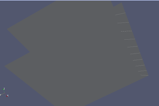
I have been viewing disjoint triangular 2D meshes, generated in Gmsh, in 3D space with ParaView. I have come across a problem where the side sets I specify appear in the jagged pattern seen in the image below. As far as I can tell, this only happens when there are multiple 2D meshes with at least one sitting outside the xy plane.
I originally thought this was a problem with MOOSE (which I am using the mesh in), however after some investigation one of the devs found it was an issue with ParaView. More details (as well as the MWE code used to generate the below image) can be found in the MOOSE issue.
This sounds like it might be a bug in the Exodus II reader. What version of ParaView are you using? ParaView’s Exodus reader recently had its first major rewrite in many years. Can you try loading your data in ParaView 5.9 (which uses the old reader) and in ParaView 5.11 (which has the most recent reader)?
Also, can you post your example data that demonstrates the problem?
Thanks for looking into it. The image above was in 5.9, the image below shows the same problem in 5.11 unfortunately. I’ve also attached the Exodus II file which produces the MWE in the images.
Hi @Kenneth_Moreland@ln53 I am calling in folks that know more than I do about Exodus and sets. However, I’m being kind of dense here. I miss what is wrong. Could you explain (like you were explaining to your artist roommate who doesn’t know visualization) what you expect, and what is wrong? Thanks. Alan
Hi @wascott , thanks for the support. Essentially those green lines in the first image (white in the second) should be a straight line along the near-right edge of the bottom square (forming a continuous boundary). Instead the wrong edge of each element appears to be highlighted, leading to the zig-zag pattern visible here.
A MOOSE dev did some more in depth investigation than I was able to, and apparently the edges are defined correctly in the Exodus file, just not being rendered in the right place.
@wascott, the core problem seems to be that the side sets for triangular elements appear to be wrong.
If you load up the mwe_in.e file that @ln53 posted, if you load it in ParaView, turn off the block, and turn on the mwe_sideset, you will get several disconnected line segments. These segments are supposed to be connected in a straight line (across one of the boundaries of the mesh).
Perhaps you could show this file to Greg S. and determine what is going wrong with this side set.
From Greg Sjaardema, the designer and developer of the Exodus format:
OK, took me too long to figure out what is happening. For a 4-noded element, we have a quad in 2D and a shell in 3D. However, when we started using 3-noded elements more, we decided for some reason to name both the 3D shell version and the 2D planar version “triangle” or “tri”.
We then determine whether it is a normal 3-sided two-dimensional triangular element, or a “5-sided” triangular shell element based on the dimensionality of the database.
In this case, we have a three dimensional database, so the “tri” elements in the element block are “triangular shell” elements.
Given a triangular shell with connectivity <1 2 3>, we have:
Face 1 is triangle front face with connectivity 1 2 3
Face 2 is triangle back face with reverse connectivity 3 2 1
Face 3 is first edge with connectivity 1 2. [ This is face 1 in a 2d triangle element]
Face 4 is second edge – 2 3
Face 5 is third edge – 3 1
The mesh you have is assuming that the elements are 3-sided elements and the “sides” are all edges, so the side numbering is off by 2. — They should have all sides as ‘5’ instead of ‘3’ to get the sideset definition that they think they have.
Thanks @wascott (and Greg S!) for the very clear answer.
Just so I’m sure on this - ParaView is behaving as expected (albeit a little confusingly), and MOOSE (which is converting the mesh from .msh to .e format) should be switching the sideset numbering to ‘5’ instead of ‘3’?
Yes, that is how I interpret it. Triangle elements have 5 “sides”, not 3. The first 2 slides are the front face and back face, respectively, followed by the 3 edges as expected. So, you need to add 2 to the numbering.