Basically, when a model is deformed, plane sections do not necessary remain plane and regular geometry can become quite irregular. Because of this, selection of an appropriate portion of a deformed model is problematical. The solution is to select using Undeformed Geometry coordinates. This allows the use of the undeformed, regular and usually simpler geometry for selection of a complex deformed geometry.
Paraview loads the deformed coordinates of the points and does not know anything about what portion of the coordinates are undeformed and/or displacement. This is in contrast to many other post-processors, which load both deformed and undeformed coordinates and can quickly display either. To display the undeformed geometry in Paraview, it is necessary to uncheck the “Apply Displacements” box in the Properties panel of the .e file. However, we are rarely interested in displaying the undeformed geometry. Therefore, to select using undeformed geometry, it is necessary to always load point displacement variables that enable us to compute the undeformed geometry. A Calculater Filter can use these displacements to reconstruct the undeformed point coordinates and to calculate a set of undeformed coordinates (Cartesian, cylindrical, etc.) After selecting a portion of the model using the undeformed coordinates, a Threshold Filter can be used to subset the model.
An illustrative example of “Selecting Deformed Geometry using Undeformed Geometry” is included below using the standard can.ex2 Paraview Exodus file
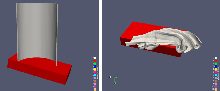
Here is the undeformed can at timepoint 0 and the deformed can at timepoint 43:
We can see here that selecting parts of the can in the crushed configuration will be very difficult
Imagine that we are most interested in the deformation of 2 parts of the can:
- We are interested in the top rim of the can as we are designing a lid for the can which will attach here
- We are interested in a section of the can where we will be embossing our company logo
We observe that the undeflected geometry is regular and the Z-coordinate can be used to select our regions of interest.
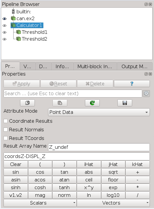
We start by calculating Z_undef(ormed), so that we can “use undeformed geometry to select deformed geometry”
Calculation of Z_undef:
For this case I subsequently ran Point Data to Cell Data so that I could select based on Cell Z_undef
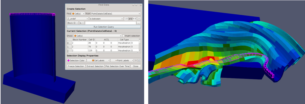
Now we can use Z_undef between -15 and -14.6 to select the can rim. This selection is shown below for both the undeformed and then the deformed geometry. Note how difficult it would be to select the rim from the deformed geometry using the deformed coordinates.
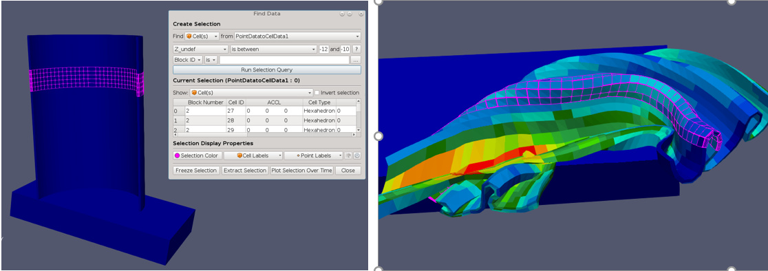
Similarly, the region of the can where the embossed logo will be placed is shown selected below for both the deformed and undeformed geometry based on Z_undef between -12 and -10. Note again how difficult it would be to select this section from the deformed geometry alone.
Of course, it might be more useful to Extract Selection for these 2 regions in the deformed geometry - also made possible by the Z_undef coordinate
Additional Notes:
This was a trivial case since the undeformed timepoint is included in the file and Extract Selection could be run on the undeformed timepoint. However, often the undeformed timepoints are not included to save disk space and this technique can be very useful. Additionally, for very large models, switching between geometries may be very costly, while the initial calculation of undeformed coordinates could be accomplished as a batch process. Also, the areas of interest often change as the investigation proceeds, so being able to dynamically select different areas in the deformed state is convenient.
A complete set of undeformed cylindrical coordinates (r_undef, theta_undef, Z_undef) could be created which would allow very flexible Selection or Subsetting of the can.
This would work even if you remeshed the can during the analysis, while freezing the Selection would not.
There are many ways of doing this, like returning to the undeformed state, selecting on regular coordinates and then Freezing the Selection, but this method is quicker and more convenient, once the initial calculation of the undeformed coordinates is accomplished. The undeformed coordinate calculations can be put into a site specific plugin to make it painless. For example, a can manufacturer might create a plugin that calculates r_undef, theta_undef and Z_undef with a single click (assuming they have a standard that Z-direction is always axial direction of can models, not an unreasonable assumption!)