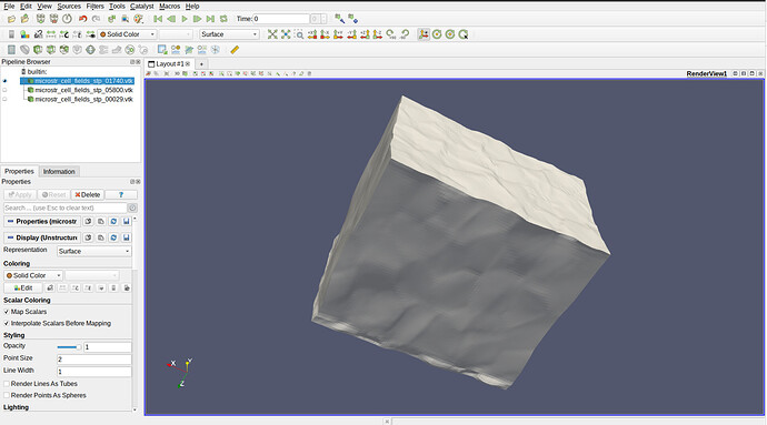
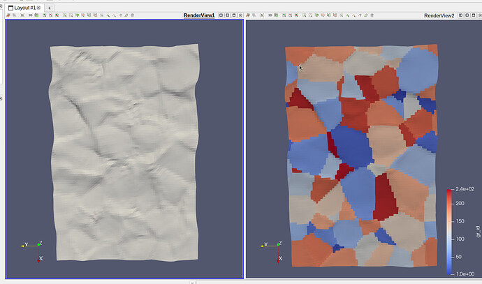
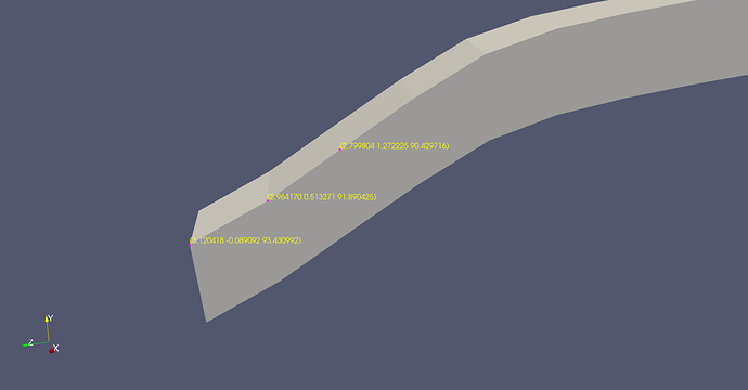
This has never happened before in my many years of using Paraview, but suddenly when I launch the program and opened a VTK file, it showed a model with surface roughness. I checked the initial state of the model and Paraview is showing smooth surfaces as it should. That means to me the program is functioning normally, except I have no idea how I enabled this and also don’t know what is the metric used to show this roughness. I couldn’t find any resources online (most likely not searching the right keywords), so I turned to here to seek some assistance. Thanks!
please share your data and versions of paraview tested
The data that generated the original figure is way too large. Here is another data. The data can be found at:
microstr_cell_fields_stp_05800.vtk (218.6 KB)
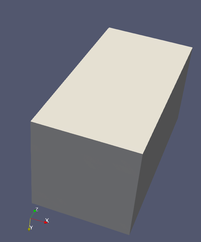
The solid color figure looks like:
The ParaView version on the window says: 5.7.0
I do not see anything special on this dataset.
Which is why I said I am not sure what I did that made Paraview show this… It has never happened before. It is sensitive to grains as the large model roughness match exactly with grain boundaries.
Unless you can share a data that show the wrong behavior, I can’t really help you.
I showed you the data and the figure it creates in Paraview 5.7.0 on Ubuntu… I don’t know what else I can provide you. It is also not a wrong behavior, in fact I think this feature is great. I just need to know how to enable/disable it and what is it actually plotting. Is it plotting points? Coordinates? The plastic equivalent strain (epvm) in the cell data?
I have no idea what you mean. Which roughness are you talking about ? Can you at least share a before/after screenshot ?
Every time before, regardless of how deformed the sample should be, when I open the VTK file, it always look smooth like this:
But today when I open Paraview, suddenly I see roughness like the figure in my first post.
This looks like a bug, please share a dataset that shows this behavior.
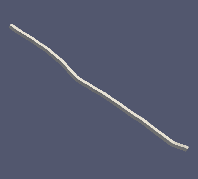
I shared the data set that you said nothing looked wrong, and the clearly distorted stick-like model above. I can try to upload this 316 MB data if you really want it.
The data you shared before shows the same behavior ? It does not look rough to me.
I am sorry but there must be some miscommunication here.
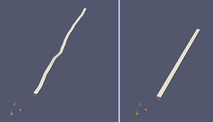
The stick model and data I showed above looks like left side in my Paraview, when it normally looks like the right:
It clearly looks not smooth. If you are saying it doesn’t look that way in your Paraview on your computer… Well that’s why I am here to find out what changed since Friday when I last used it.
To make it complicated, as I said, it is consistent with some sort of data in the model, maybe the points data because the simulation that created this will evolve the points and cells and etc if needed. But the inconsistent thing is this has never happened before.
Here is another side-by-side to illustrate that the roughness matches with grains.
Let me know if there is any specific files that you would like me to upload for you to look at. As i said, if you want, I can upload this 316 MB data if needed. But I am observing the same behavior for the data I shared above so I hope that would be enough.
In my ParaView, it looks like on the left, but to me it looks like this is what is expected according to the coordinates of the points:
I’ve no idea why it would not looks like this before.
Ok, so at least this is now the expected behavior. I do like it. I think there is not much merit in finding out why it wasn’t doing this before… But I would like to know if there is a way to not show this deformed coordinates for better visualization of cell data?
But it is not deformed. This is where the data is in your file itself.
I cant test old version of ParaView rn, so you will have to test that on your side.
When I say deformed, I mean in comparison with undeformed, smooth surface state, this is deformed. I don’t mean deformed as in bug. Are you saying given what data is available in the VTK file, there is no way Paraview would visualize this any differently because the coordinates of the points are deformed?
But this will make selecting cell data for plotting difficult. From our discussion, I found this thread: Create Undeformed Geometry Coordinates for use in Selecting Deformed Geometry (Exodus example)
But I cannot find this “apply displacement” option. To be fair, I am also not working with a .e file, whatever that file is supposed to be. I believe the reason this deformed state shows up so clearly is because in this simulation, the model is extremely deformed. In my previous attempts, I have not gone this far. If I were to output the initial coordinates of the points as well, is there a way to have the model not show deformed points, and show the initial point coordinates while plotting cell data over it?
I think you might be referring to flat shading?
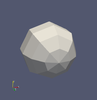
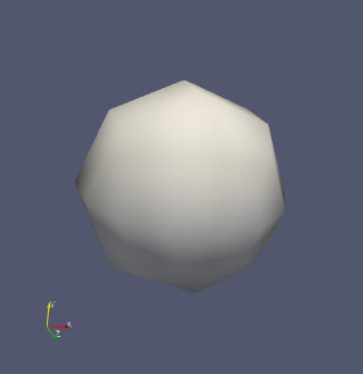
This is controlled in the Properties panel under Lighting, Interpolation, which is an advanced parameter, so you have to click the little gear icon at the top.
I tried flat or Gouraud, but unfortunately it didn’t have as drastic of an effect as yours showed.
I think it is ok, if I need to, I simply overwrite the point coordinate data with the undeformed state. It is unfortunate that I have to do such a manual workaround, but it is what it is.
