(1) We start with decomposed OpenFOAM results. We cannot rerun the OpenFOAM simulation with any changes in settings.
(2) We load the results into ParaView as a decomposed case.
(3) The goal is to produce a Contour plot (for example, U_z = 2 m/s) without gaps (“seams”) at the Processor Boundaries.
(4) I have tried all kinds of advice I have found in forums (for example, MergeBlocks > Ghost Cell Generator > Cell Data to Point Data > Contour), but nothing seems to work.
This is a fundamental question, so there should be some kind of documentation on it. If you like, I can provide screenshots for the OpenFOAM tutorial incompressible/simpleFoam/motorBike
Important note: Pretend the test case is so large that it is not practical to create one large dataset on the client machine, thereby removing the Processor Boundaries. My actual goal is to write VTK code (rather than using ParaView) so a separate processor will compute the contour in each processor region. I believe this must be done using Ghost Cells, so I would like to see it work in a ParaView pipeline first.
It turns out the limit for uploads is 10 MB (not 20 MB), so I have created a highly compressed version of the test case, and it is attached as motorBikeCoarseDel2.tar.gz
I have made the mesh coarser, and after running, I deleted 4 of the 6 Processor Regions. I also deleted some unnecessary time directories and other files.
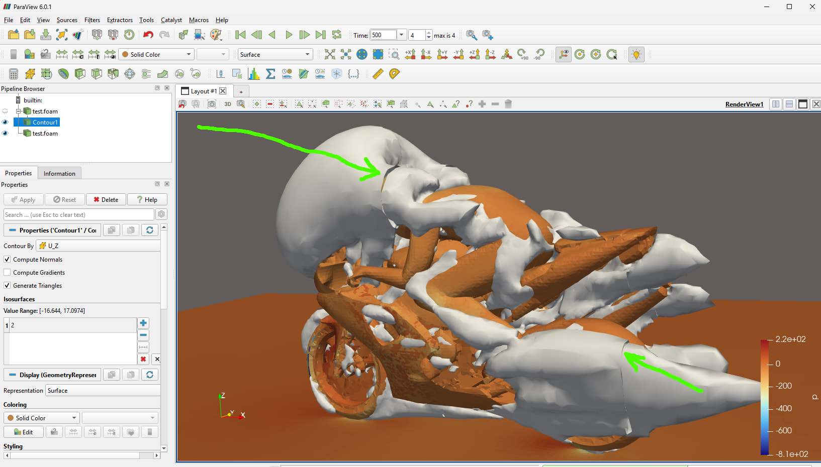
This compressed version still illustrates the same issue as the original version, as indicated by the green arrow in the image below.
In case anyone is interested, here are the parameters I changed in order to achieve the small size of the attached tar.gz file:
Thanks! Do you know of any OpenFOAM tutorials that do not have this problem? (I selected the motorBike because Google AI and others told me it was the most popular OpenFOAM tutorial)
I believe this must be done using Ghost Cells, so I would like to see it work in a ParaView pipeline first
This is indeed related to ghost cells. Related to a separate project, I’ve made some more thoughts on this.
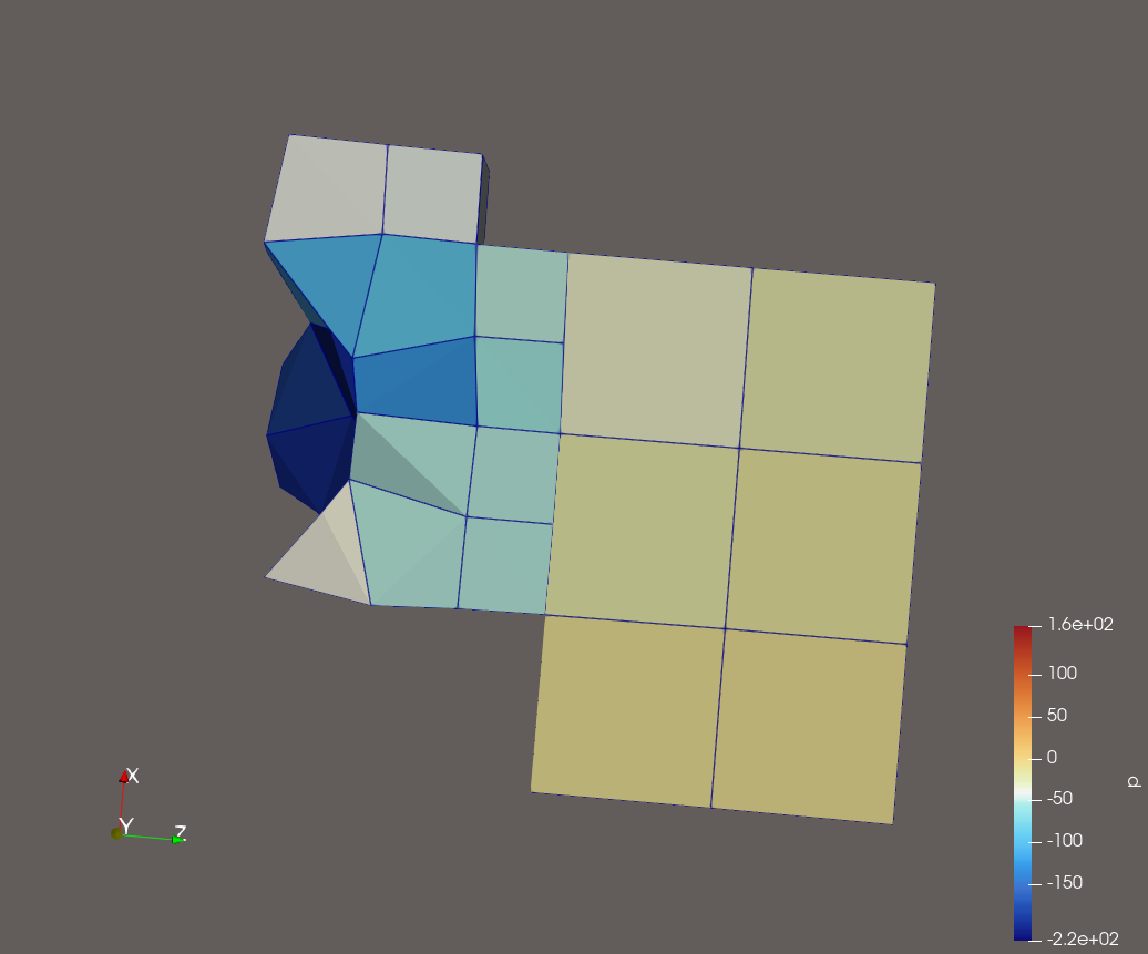
The fundamental problem is that the data sets for each rank are actually handled independently and separately. For the VTK (openfoam) reader part, it actually fires off a reader/parser for handling each of the processor ranks. However, that is not the real issue. The problem is that there no matching up of the processor boundaries and the corner points that you’d need to have proper connectivity between the domains. The lowest hanging fruit that will only help somewhat, would be to also parse out the processor patches. For example, could mark the face points of the neighbour processor side as being ghost points. But this still will not get you the proper contours across processor boundaries.
AFAIK to get proper contours across processor boundaries, you do need ghost cells. However, it seems that these ghost cells really the same type, shape etc as the original cells. Even working from within OpenFOAM itself (where we have complete information about the domain connectivity, shared points etc.), this would require exchanging an entire cells, with their supporting points between neighbouring ranks. Not sure if you also need to avoid duplicate points within these ghost cells.
My current working idea (which doesn’t really fit with the original problem) would be an OpenFOAM solution. With globalMeshData, mergePoints we can determine globally consistent numbering, global shared points etc. Could use this information when writing out a VTK-compliant dataset (eg, VTKHDF) in parallel.
I have played with several ideas of adding in ghost cell information as an auxiliary output file (from OpenFOAM), but this has the same problems as mentioned in the last post. The ghost cell concept in VTK works great for codes that already use ghost (halo) cell representations internally (and probably primitive cell types as well). The ghost cell representation definitely does not fit for codes like OpenFOAM that don’t use halo cells, but use what are essentially halo faces (which works, since the neighbour cell information reduces to its coefficients there).
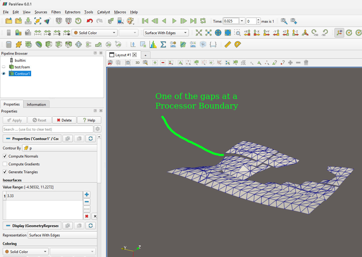
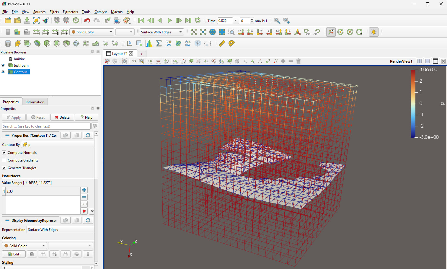
I have created a modified form of the OpenFOAM “cavity” tutorial, and it is attached, including results. It has 27 Processor Regions. It does not have the T junction problem. For time = 0.025, here is a contour for p = 3.33. Is it possible to use Ghost Cells in the ParaView pipeline to remove the gaps at the processor boundaries?
Would be interesting to see how well (how fast) the ghost cells algorithm works. Looks like a nasty search problem - would be nice if we could help seed it with information from the processor boundaries.
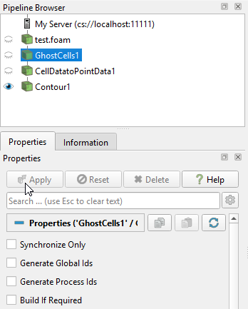
(3) Connect to local server and setup pipeline as shown in the screenshot below. Note that “Build If Required” is unchecked at the bottom of the screenshot
(4) Then you can check and uncheck “Build If Required” and click Apply, and the 3D scene will show the seam repairing switched off and on, correspondingly.
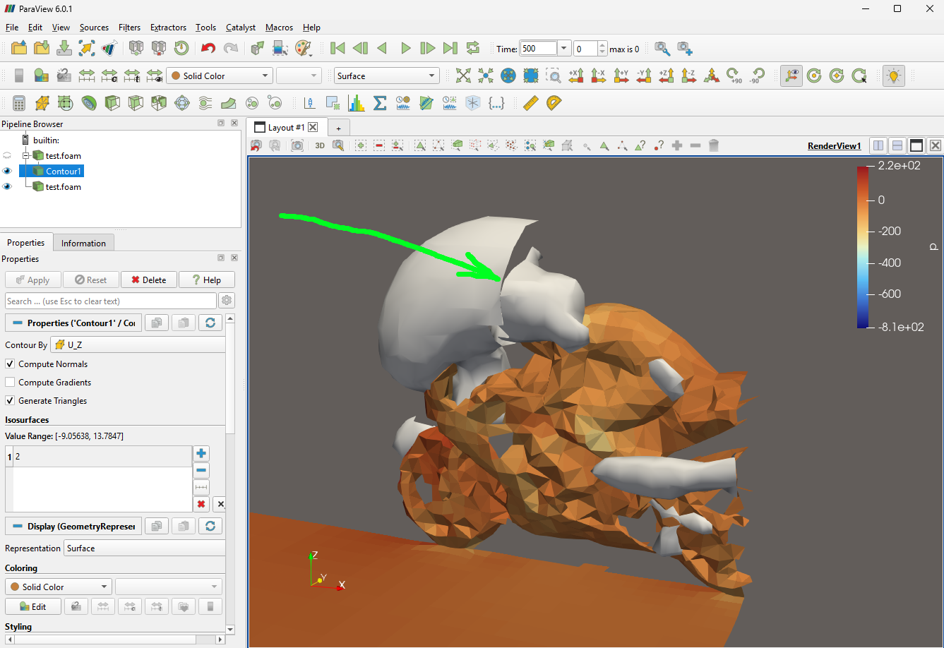
The attached gif flips back and forth between two images, one with the seams repaired, and one without the repairs. This is for the original OpenFOAM tutorial incompressible/simpleFoam/motorBike without any modifications. The ghost cell checkbox (on the left) that I mentioned above can be seen switching between its two states as well. (This is for time = 500)
By the way, I just wanted to mention that the first test.foam in the pipeline is the internalMesh, and the last test.foam is just a set of surfaces so we can see the motorBike, rider and road. Also I wanted to mention that some references use the term “rips” for the gaps/seams.
Having looked at this a bit in the past, OpenFOAM datasets appear to produce enough information to define a GlobalPointID array in the reader. If you have those, the GhostCellsGenerator will be way faster because it won’t have to do the very costly point matching step across ranks. We had plans at one time to implement GlobalPointID array reading in the parallel OpenFOAM reader but the project got shelved.
Hi @cory.quammen - this sounds intriguing. The regular matching of face points on processor-processor boundaries is reasonably straightforward, it’s just the points shared between 3+ ranks that would be more difficult in VTK (I think).
We have OpenFOAM results for a case with 24 Processor Regions. I ran 24 copies of the pvserver
mpiexec -np 24 pvserver
I was able to calculate the iso-surface for time = 100, but when I switched to time = 4000 the machine became unresponsive. Keep in mind I had installed Microsoft MPI, as I mentioned above, so I was disappointed to see this behavior.