Hi all,
Any one who help me to calculate the Euler characteristics and Betti number of a 3D object using TTK on ParaView? Thanks
@kokebdese There is an … overkill way to do it.
The Discrete Sandwich module compute them and print them when the debug level is high enough (4 or more)
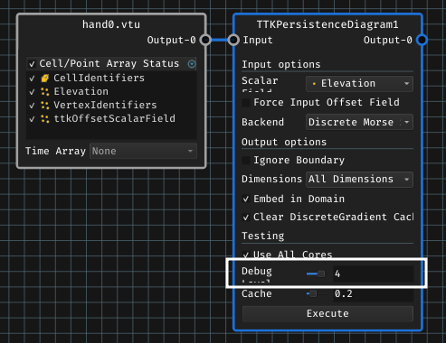
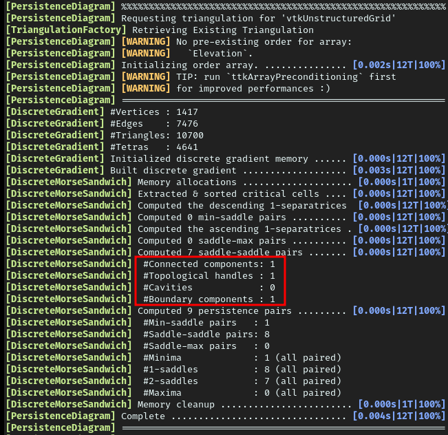
Then, in the execution log (visiblie in the terminal launching ParaView), you will have the corresponding section:
Which corresponds to the first Betti numbers.
From my memory, there is a simpler way to compute them in 3D as in a simplicial complex, by playing with the number of connected components, vertices, edges, triangles and tetra, as well a the Euler characteristics, you just have some addition / subtraction to do.
@Charles_Gueunet, Thank you for interesting answer, however, what is Discrete Sandwich module? As I am new to the ParaView, I need to know how to get that. Thanks!
@kokebdese no problem ![]()
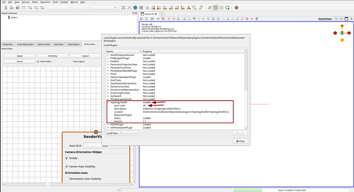
Do you have TTK enabled on your ParaView ?
Tools > Manage Plugins…
Once it is done, you should be able to access TTK filters, including the TTKPersistenceDiagram one.
As you can see in my first anwer, the TTKPersistenceDiagram filter has a Backend option which by default is set to Discrete Morse Sandwich. This is the backend used for the computation of the persistence pairs, which record the most topological events. This module is also used in other TTK filters, so you may encounter this options in others filters while playing around. This module compute and print the Betti number when the debug level is 4 or more.
@Charles_Gueunet. Thank you for your continuous support.
I face another challenge. I want to play with 3d segmented (nuclide of cell) data using electron microscope. I processed it using different image processing algorithm using matlab and finally I transferred the .mat format data to .stl format (which the ParaView able to read). However, the TTK persistent diagram filter is inactive for .stl files. Could you help me on this pls? Thank you!
You need your mesh to be a valid 2 or 3 simplicial complex.
In simple terms, here you want to Extract Surface and Triangulate you mesh.
Be careful, you should have a clean mesh before using TTK filters. If you encounter crashes or errors, please have a look at the ManifoldChecker example
@ Charles Gueunet
Thank you, but I couldn’t get your explanation? How could I able to know whether my data is valid 2 or 3 simplicial complex? What do you mean by clean mesh? Thanks
@ Charles_Gueunet, How do I Extract Surface and Triangulate my mesh? May I know how could I do that? I am new to ParaView?
Thank you for understanding.
How could I able to know whether my data is valid 2 or 3 simplicial complex?
If you can share your data, I can have a quick look for you, let’s focus on easier parts first. The idea is to take inspiration from the Manifold Checker example given above.
What do you mean by clean mesh?
I mean a mesh composed only of triangles, which do not overlap, and have a good connectivity (not 3 triangles connected on a same edge Y , not 2 triangles connected by a single point >< ) …
You may have a look at the definition of a Manifold (here a 2-manifold).
How do I Extract Surface and Triangulate my mesh? May I know how could I do that? I am new to ParaView?
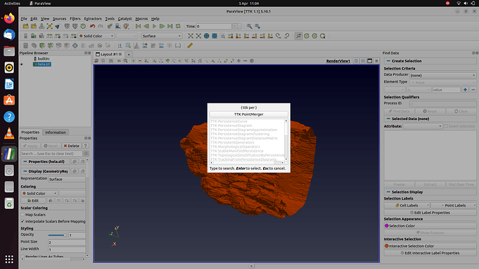
Those are ParaView filters to apply to your mesh before applying a TTK filter. For this, you need select you mesh on the pipeline, then with Ctrl+Space you can choose a new filter. Select the Extract Surface filter and apply it. Then, on the result, Ctrl+Space again, Triangulate and press apply.
Hi @Charles_Gueunet:
I really appreciate in the way you are helping me to understand a TTK. Now, I got all what you mean. However, even though I have tried to go though the mesh tutorials, still I couldn’t able to reproduce it on my own data set. Here (with the link: hela.stl - Google Drive) is my sample data in .stl format (since it is >4MB, I couldn’t able to upload it here [file name: hela.stl]) and could you help me in checking for Manifold? Thank you.
Hello @kokebdese
I have applied the ttkManifoldChecker on your mesh and obtained the following arrays:
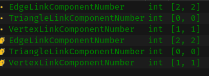
As we can see, all of them are constant. Basically, for a surface mesh, this means that the neighborhood is always valid, your mesh is manifold.
Then we want to compute the betti numbers. We have seen the idea is to use the persistence diagram filter with a debug level of 4 to get this information, but this filter expect a scalar field, so we create a dummy one using a calculator, an elevation, a random …
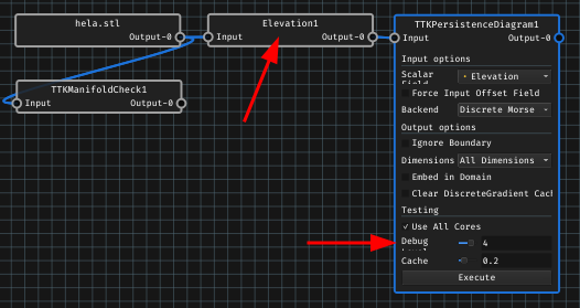
During this computation, I have the following output:
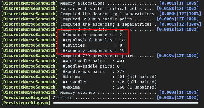
So the first betti numbers are: 2 , 18 , 0
We can use the connectivity filter to see that we have indeed to connected components on this data set. Of course, there is no void on a surface mesh. It seems there are 18 handles also. We could try to extract them if needed but this would be some work.
@Charles_Gueunet
Hey,
I thank you so much! You are making me to love TDA [TTK], which I believe is a very central topic of my current study work. I hope to continually see your kind support like this.
Hi
What was the reason to consider a debug level of 4 than any other number to calculate the betti number?
Thanks
Hello,
This is simply because the corresponding debug message is only displayed with a debug level of 4 or more, see the corresponding line.
@Charles_Gueunet
Thank you!
Hey
“It seems there are 18 handles also” Does these handles are all holes?
@kokebdese The term of “hole” usually refer both to handle and void/cavities. As there is none here, I would assume that 18 handles + 0 cavities means 18 holes
@Charles_Gueunet: Thank you!
@Charles_Gueunet
Hey
Is there a way to save the values displayed in the Terminal or it that the only window where the values are displayed? Thanks
