I would like to have a stl file (which represents a solid rigid) which follows the motions of another rigid object attached to it, for which I have time history of the displacement. Is there a simple way to do it?
Not simple but may be doable with the animation view, especially the “python” mode of it.
Another way to look at it is to use a glyph instead, you can show you stl as a “glyph” on a point which is attached to your rigid.
Thanks a lot for your answer. I am quite new to paraview. How would you impose a motion to a glyph?
Could you share your data so I can give you an example ?
I attach the stl file; I would like the (0,0,0) of the stl file to follow a time series in six DOF. How would it be better to send you the time series of the six degrees of freedom?
(Attachment WINDMOOR_vis.stl is missing)
Nothing got attached.
Here is an example:
data:
https://data.kitware.com/api/v1/file/5afd93688d777f15ebe1b48a/download
cow.vtp (59.0 KB)
state file:
state.pvsm (416.3 KB)
Result:
Hi,
That is exactly what I want, but I am not able to load the state… what were the steps you followed?
Thanks again,
Irene
Which version of ParaView are you using ?
I tried with both 5.9.1 and 5.10.1
Steps for 5.10.1
- run ParaView
- open can.ex2, Apply
- open cow.vtp, Apply, hide the cow
- Using selection tools, select a single point on the red part of the can
- Extract Selection, Apply
- Change the representation of the ExtractSelection to “3D Glyphs”
- Instead of Arrow, Choose pipeline connection as the glyph type (in display properties)
- Choose the cow as the actual glyph
- Press play to play the animation
hth

There is an orient property on the glyph that you can use, but you need a vector in the right direction on the point you selected.
Thanks again, but I do not understand what you mean by ‘a vector in the right direction on the point you selected’. Also, I did not select a point, but a polygon: could that be an issue?
Hi,
Please share your data, it is hard to explain without it.
It was too heavy, so I share it here: ![]() WINDMOOR_vis.stl
WINDMOOR_vis.stl
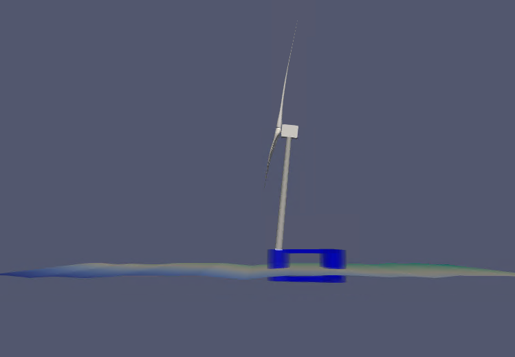
And the tower (the stl should follow the base of this tower): ![]() paraview
paraview
Please let me know if something else is needed
Thanks again!
Irene
I managed to do something, not sure this is what you want:
Extracting a cell is actually a good thing, because you need it to do that. Here is more or less what you need:
- On your extracted cells, add a “Extract Surface” filter
- Add a GenerateSurfaceNormals, Apply
- Select a single point, ExtractSelection, Apply
- Add a Transform, change the Transfrom type to “Rotate around origin”
- Pick the origin on the middle of the cell and rotate by -90 deg in Y
- Use 3D glyphs representation as before, but enabled “orient” and choose your “rotated” normals
Its a complex pipeline, but I hope it helps you achieve your goal.
Hi,
Yes, this is what I want; actually, the blue tower should be at the upfront column (so -35.218m translated in x), and at z = 15.5m. But other than that it is what I want. I did not manage to do it; I get lost on the ‘Select a point’ and then on the ‘Transform’ point. Where should I select the point from?
I think I am almost there, but that a small detail is escaping…
Thanks again!
Irene
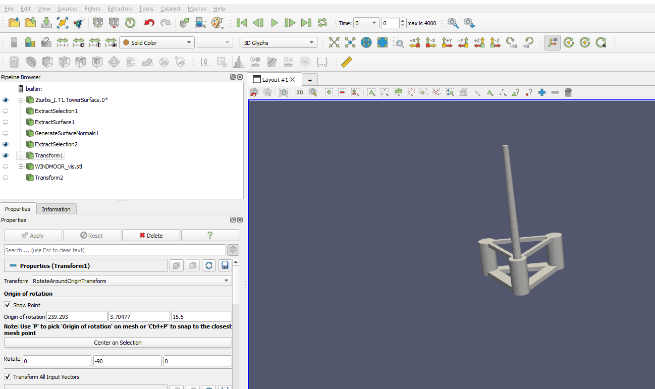
Here is how to select a cell, compute the normals and select a point, then apply a transform
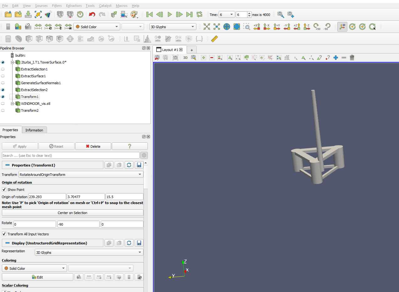
Great, perfect, I am doing the same as you, but then my stl, when I include it as glyph, rotates, but does not translate anymore. In the gif you sent I could not appreciate if it was moving or not with it…
This is what I get following the steps you mention (and trying to align the stl with the tower)
Please share your statefile. Which version of ParaView are you using ?