Use array of pointers to dereference the data needed by Catalyst

@Andy_Bauer @utkarsh.ayachit @mwestphal @Francois_Mazen @nicolas.vuaille or anyone experienced in using catalyst, please help me out.

I wanted to use Catalyst for in-situ visualization in a C astrophysical hydrodynamics code called PLUTO. I have been able to successfully use catalyst by modifying the CFullExample code provided with minimal changes in the original source code of PLUTO.

The CFullExample simulation code uses a grid and field data that is structured in such a way that is compatible with Catalyst (vtk). Unfortunately, PLUTO simulation grid and field data arrangement is not natively compatible with Catalyst. Therefore, I had to copy the grid data and the field data to the compatible structures as given in the Example code. These structures are:

typedef struct Grid
{
  uint64_t NumberOfPoints;
  uint64_t NumberOfCells;
  double* Points;
  int64_t* Cells;
} Grid;

typedef struct Attributes
{
  // A structure for generating and storing point and cell fields.
  // Velocity is stored at the points and pressure is stored
  // for the cells.
  double* Velocity;
  float* Pressure;
  Grid* GridPtr;
} Attributes;

Therefore, each time there is a update of grid or field data, I had to copy the data from PLUTO simulation and update the members of these data structures. Then I’m able to get the correct results when using the code provided in CatalystAdaptor.h.

For example, the following line in CatalystAdaptor.h assumes that the (point) data, which is already structured in vtk compatible format, is present at the memory location of the pointer to the array grid->Points. As a result, I had to create a vtk compatible grid->Points array which is properly structured by copying data from native PLUTO arrays.

Copying every time from PLUTO arrays before Catalyst accesses the data makes the code slow and also creates redundant memory footprint containing the same data.

conduit_node_set_path_external_float64_ptr_detailed(mesh, "coordsets/coords/values/x",
    /*data=*/grid->Points, /*num_elements=*/grid->NumberOfPoints, /*offset=*/0,
    /*stride=*/3 * sizeof(double), /*element_bytes=*/sizeof(double),
    /*endianness=*/CONDUIT_ENDIANNESS_DEFAULT_ID);

The way out I think would be to make every element of grid->Points array (similarly other grid/field data) to not contain values but pointers to memory addresses of the required values from the original native PLUTO arrays. This eliminates the need for copying during every update (as the simulation already updates them). However, this requires rather than direct reading of data at the location of grid->Points, dereferencing the addresses contained by every element in grid->Points.

This is where I’m stuck because using the functions in CatalystAdaptor.h doesn’t seem to do this job.
Please help. I’m new to Catalyst.

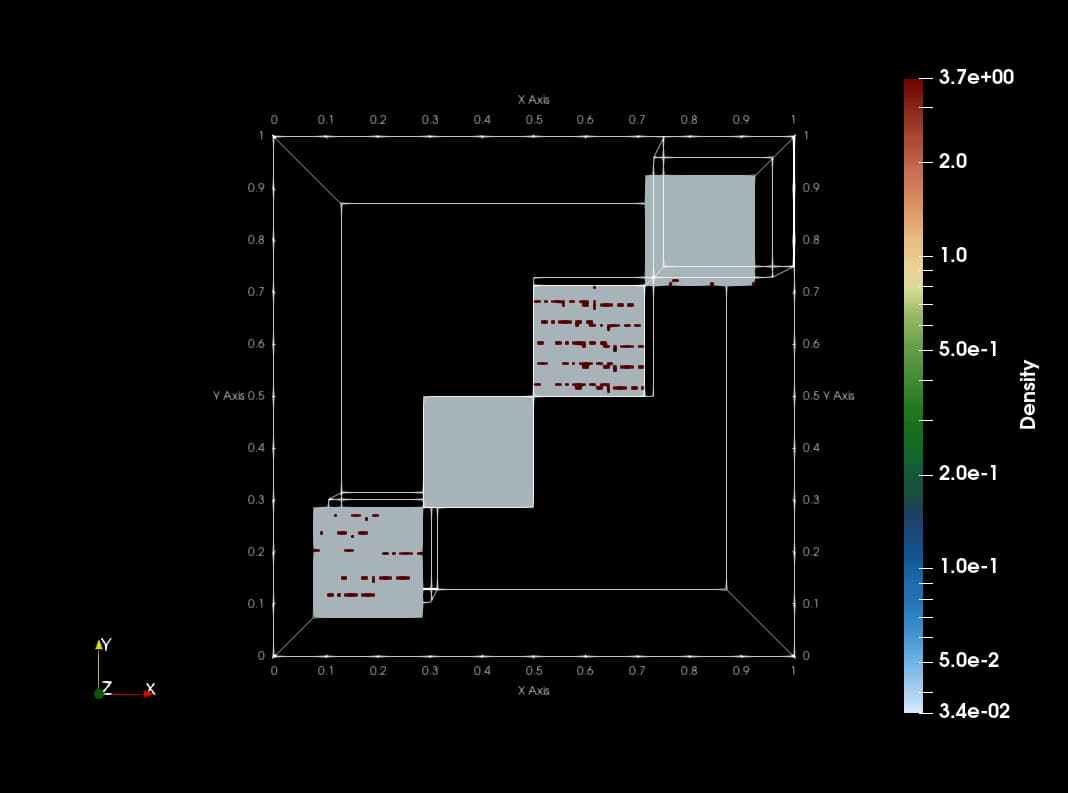
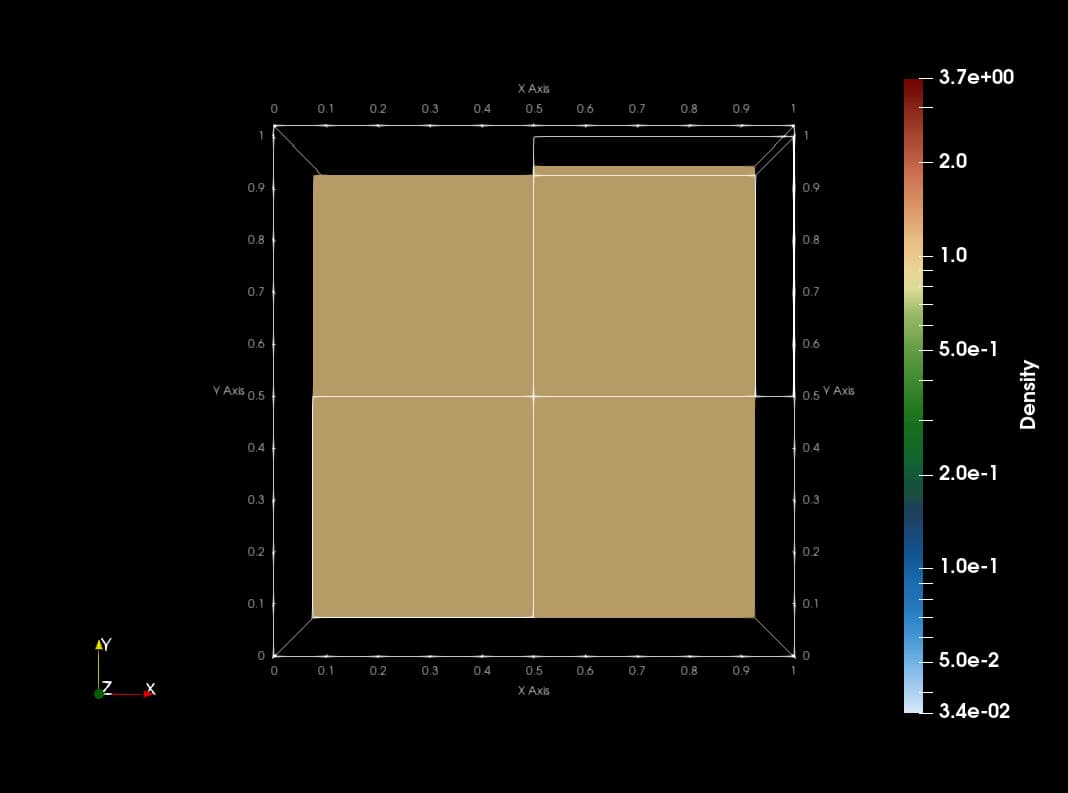
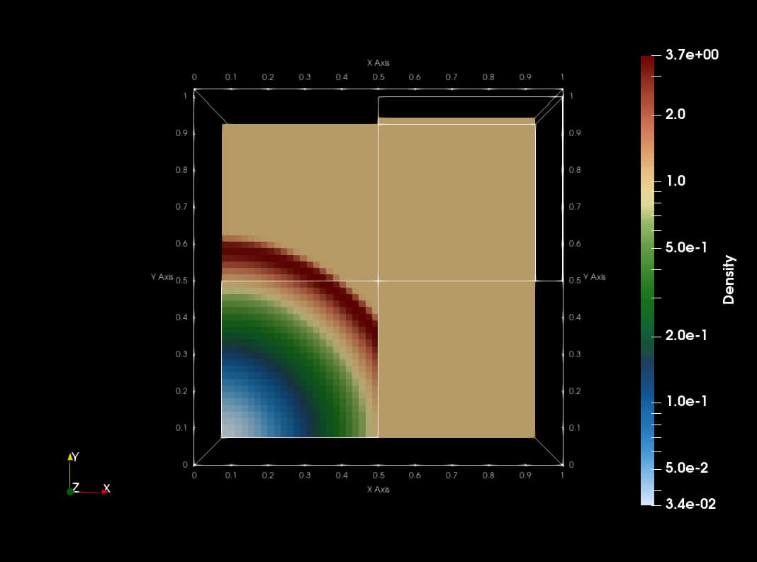
This animation is made with png dumps from a run of the PLUTO code. The code uses Catalyst to create slices of blastwave formation in real time. The current implementation copies data from native PLUTO arrays to vtk compatible array structures which makes the code slow with redundant memory footprint.

Hello @dutta-alankar

This is great to see Catalyst usage in astrophysical hydrodynamics!

Could you please describe the data arrangement in PLUTO, in order to find a suitable way to avoid data copy with conduit?

The conduit set_external_xxx methods are the correct ways to avoid data copy, by using the offset and stride parameters accordingly. You can look at the conduit documentation here: Data Ownership — Conduit 0.8.8 documentation

Best,

François

This is perhaps possible by using offset and strides different from that provided in CFullExample. Can you please help me with that?

PLUTO has a struct called Grid which stores grid properties and another struct called Data which stores field properties. All the data are cell values (I have put these PLUTO structs at the end).

In PLUTO, the data is arranged in z-y-x format (x is fastest changing) while in CFullExample as far as I can understand from the code is in x-y-z format (z is fastest changing).

Since for each cell, I know the left and the right edges created by PLUTO, I was able to create the point data needed by Catalyst. Then I used the grouping of point indices provided from CFullExample code to create the Cells. I’m providing the relevant sections of this code.

Info:

  • Number of cells: NX1 times NX2 times NX3 along x, y, z respectively.
  • IDIR is x-direction JDIR is y and KDIR is z
  • For x-direction, local domain (excluding ghost cells) in each processor starts from index IBEG with respect to the entire global array and ends at IEND (similar for other directions).
  • For grids, Catalyst compatible struct is cgrid while native PLUTO struct is just grid
  • IDOM_LOOP is a macro in PLUTO defined as,
    #define IDOM_LOOP(i) for ((i) = IBEG; (i) <= IEND; (i)++)
    Similar macros exist for other directions.

Point data is assigned to a Catalyst compatible structure called cgrid (most of it is taken from CFullExample) from PLUTO cell data

unsigned int numPoints[3] = {NX1+1, NX2+1, NX3+1};
for (i = IBEG-1; i <= IEND; i++)
  {
    for (j = JBEG-1; j <= JEND; j++)
    {
      for (k = KBEG-1; k <= KEND; k++)
      {
        cgrid->Points[counter] = grid->xr[IDIR][i];
        cgrid->Points[counter + 1] = grid->xr[JDIR][j];
        cgrid->Points[counter + 2] = grid->xr[KDIR][k];
        counter += 3;
      }
    }
  }
  cgrid->NumberOfPoints = numPoints[0] * numPoints[1] * numPoints[2];

Field data which is Catalyst compatible with strides and offset identical to CFullExample is assigned in the following way:

  cattributes->VelocityX    = (double*)malloc(sizeof(double) * numCells);
  cattributes->VelocityY    = (double*)malloc(sizeof(double) * numCells);
  cattributes->VelocityZ    = (double*)malloc(sizeof(double) * numCells);
  cattributes->Pressure     = (double*)malloc(sizeof(double) * numCells);
  cattributes->Density      = (double*)malloc(sizeof(double) * numCells);
    
  unsigned int i, j, k;
  int counter = 0;
  IDOM_LOOP(i)
  {
    JDOM_LOOP(j)
    {
      KDOM_LOOP(k)
      {
        cattributes->VelocityX[counter]   = d->Vc[VX1][k][j][i];
        cattributes->VelocityY[counter]   = d->Vc[VX2][k][j][i];
        cattributes->VelocityZ[counter]   = d->Vc[VX3][k][j][i];
        cattributes->Pressure[counter]    = d->Vc[PRS][k][j][i];
        cattributes->Density[counter]     = d->Vc[RHO][k][j][i];
        counter++;
      }
    }
  }

Following are the two PLUTO structs (Grid and Data respectively):

typedef struct Grid_{
  double xbeg[3], xend[3];           /**< Leftmost and rightmost points in local domain. */
  double xbeg_glob[3], xend_glob[3];  /**< Leftmost and rightmost point in the global domain. */
  double *x[3], *x_glob[3];   /**< Cell geometrical central points. */
  double *xr[3], *xr_glob[3]; /**< Cell right interface. */
  double *xl[3], *xl_glob[3]; /**< Cell left interface. */
  double *dx[3], *dx_glob[3]; /**< Cell width.  */ 
  double *xgc[3];          /**< Cell volumetric centroid 
                             (!= x when geometry != CARTESIAN).  */
  double  ***dV;           /**< Cell volume.  */
  double  ***A[3];         /**< Right interface area, A[i] = \f$A_{i+\HALF}\f$. */
  double  **dx_dl[3];      /**< dx/dl (dl = length), used for gradient-like operators */
  double *rt;              /**< In spherical coordinates, gives \tilde{r} */
  double *sp;              /**< In spherical coordinates, gives fabs(sin(th))
                                at a j+1/2 interface */
  double *s;               /**< In spherical coordinates, gives fabs(sin(th))
                                at the cell center */
  double *dmu;             /** < In spherical coordinates, gives the \theta
                                 volume = fabs(cos(th_m) - cos(th_p)) */
  double *inv_dx[3];       /**<      */
  double *inv_dxi[3];      /**< inverse of the distance between the center of 
                             two cells, inv_dxi = \f$\DS \frac{2}{\Delta x_i +
                             \Delta x_{i+1}}\f$.     */
  double dl_min[3];      /**<  minimum cell length (e.g. min[dr, r*dth,
                            r*sin(th)*dphi] (GLOBAL DOMAIN).  */
  int np_tot_glob[3]; /**< Total number of points in the global domain 
                        (boundaries included). */
  int np_int_glob[3]; /**< Total number of points in the global domain 
                        (boundaries excluded). */
  int np_tot[3];      /**< Total number of points in the local domain 
                           (boundaries included). */
  int np_int[3];      /**< Total number of points in the local domain 
                           (boundaries excluded). */
  int nghost[3];      /**< Number of ghost zones. */
  int lbound[3];      /**< When different from zero, it specifies the boundary
                           condition to be applied at leftmost grid side where  
                           the physical boundary is located.
                           Otherwise, it equals zero if the current 
                           processor does not touch the leftmost physical boundary. 
                           This evantuality (lbound = 0) is possible only
                           in PARALLEL mode.  */ 
  int rbound[3];      /**< Same as lbound, but for the right edge of the grid. */
  int gbeg[3];        /**< Global start index for the global array. */
  int gend[3];        /**< Global end   index for the global array. */
  int beg[3];         /**< Global start index for the local array. */
  int end[3];         /**< Global end   index for the local array. */
  int lbeg[3];        /**< Local start  index for the local array. */
  int lend[3];        /**< Local end    index for the local array. */
  int uniform[3];     /* = 1 when the grid is cartesian AND uniform everywhere  */
  int nproc[3];       /**< number of processors for this grid. */
  int rank_coord[3];  /**< Parallel coordinate in a Cartesian topology. */
  int level;          /**< The current refinement level (chombo only). */
  int *ring_av_csize; /**< The chunk size when RING_AVERAGE is turned on */   
  char fill[376];   /* useless, just to make the structure size a power of 2 */
} Grid;
typedef struct Data_{
  double ****Vc;    /**< The main four-index data array used for cell-centered
                        primitive variables. The index order is
                        <tt>Vc[nv][k][j][i]</tt> where \c nv gives the variable
                        index while \c k,\c j and \c i are the
                        locations of the cell in the \f$x_3\f$,
                        \f$x_2\f$ and \f$x_1\f$ direction. */
  double ****Uc;    /**< The main four-index data array used for cell-centered
                       conservative variables. The index order is
                       <tt>Uc[k][j][i][nv]</tt> (\c nv fast running index)
                       where \c nv gives the variable index, \c k,\c j and \c i
                       are the locations of the cell in the \f$x_3\f$,
                       \f$x_2\f$ and \f$x_1\f$ direction. */
  double ****Vs;    /**< The main four-index data array used for face-centered
                         staggered magnetic fields. 
                         The index order is <tt>Vc[nv][k][j][i]</tt>,
                         where \c nv gives the variable index, \c k,\c j and \c i
                         are the locations of the cell in the \f$x_3\f$,
                         \f$x_2\f$ and \f$x_1\f$ direction. */
  double ****Vuser; /**< Array storing user-defined supplementary variables 
                         written to disk. */ 
  double ***Ax1;    /**< Vector potential comp. in the \f$x_1\f$ dir.*/
  double ***Ax2;    /**< Vector potential comp. in the \f$x_2\f$ dir.*/
  double ***Ax3;    /**< Vector potential comp. in the \f$x_3\f$ dir.*/
  double ****J;     /**< Electric current defined as curl(B). */
  double ***Tc;     /**< Dimensionless temperature array (used for TC) */
  double ***q;      /**< Electric charge density (only for ResRMHD)    */
  unsigned char ***flag; /**< Pointer to a 3D array setting useful integration
                              flags that are retrieved during integration. */

  /* -- Particles-related quantities -- */

  struct particleNode_ *PHead;   /* Must use full declaration since particleNode
                                    typdef will come later on. */

  double ****Fcr;   /**< A four-element 3D array used to compute the three
                         components of the force and the energy source term
                         of the CR feedback on the fluid. */
  double ****Jcr;   /**< The CR current density 3D array. */
  double ***qcr;    /**< The CR charge density 3D array. */
  
  double ****Fdust; /**< Drag force (dust particles only)   */
  struct Particle_ **pstr;  /**< Used to convert a linked list to array (useful ?) */

/* EMF  */
  double ***Ex1; /**< cell-centered emf used in CT averaging or CR particles */
  double ***Ex2; /**< cell-centered emf used in CT averaging or CR particles */  
  double ***Ex3; /**< cell-centered emf used in CT averaging or CR particles */

  struct ElectroMotiveForce *emf;

/* Others */
  struct timeStep_  *Dts;

  /* ForcedTurb */
  struct ForcedTurb *Ft;
  
  void (*fluidRiemannSolver)     (const Sweep *, int, int, double *, Grid *);
  void (*radiationRiemannSolver) (const Sweep *, int, int, double *, Grid *);
  char fill[78];  /* make the structure a power of two.  */
} Data;

I guess you are working with rectilinear grid. You can look at the associated Blueprint example: Mesh Blueprint — Conduit 0.8.3 documentation

For the point, you can directly set to the corresponding grid->xr data:

coordsets: 
  coords: 
    type: "rectilinear"
    values: 
      x: (set_external_... of grid->xr[IDIR])
      y: (set_external_... of grid->xr[JDIR])
      z: (set_external_... of grid->xr[KDIR])
topologies: 
  mesh: 
    type: "rectilinear"
    coordset: "coords"

For the field, offset and stride will not be sufficient to map from an z-y-x data to x-y-z order. Maybe the easiest way is to inverse your coordinates (x: grid->xr[KDIR]) and z: of grid->xr[IDIR]), then use the set_external with the raw data:

...
fields: 
  VX1: 
    association: "element"
    topology: "mesh"
    volume_dependent: "false"
    values: (set_external_... of d->Vc[VX1])
 VX2: 
    association: "element"
    topology: "mesh"
    volume_dependent: "false"
    values: (set_external_... of d->Vc[VX2])
 VX3:
   ...

Hope this helps!

Best,
François

Thanks a lot for the help. The conduit blueprint was helpful and indeed the grid structure I’m using is rectilinear. I have changed my code according to what you suggested but now I get slice plots which doesn’t make much sense (attached at the end).

Here’s the relevant parts of my changed code in CatalystAdaptor.h. Please let me know what’s going wrong.

Adding coordinates:

  // add coordsets
  conduit_node_set_path_char8_str(mesh, "coordsets/coords/type", "rectilinear");
  conduit_node_set_path_external_float64_ptr_detailed(mesh, "coordsets/coords/values/x",
    /*data=*/&(grid->xr[KDIR][KBEG-1]), /*num_elements=*/NX3+1, /*offset=*/0,
    /*stride=*/ sizeof(double), /*element_bytes=*/sizeof(double),
    /*endianness=*/CONDUIT_ENDIANNESS_DEFAULT_ID);
  conduit_node_set_path_external_float64_ptr_detailed(mesh, "coordsets/coords/values/y",
    /*data=*/&(grid->xr[JDIR][JBEG-1]), /*num_elements=*/NX2+1, /*offset=*/0,
    /*stride=*/ sizeof(double), /*element_bytes=*/sizeof(double),
    /*endianness=*/CONDUIT_ENDIANNESS_DEFAULT_ID);
  conduit_node_set_path_external_float64_ptr_detailed(mesh, "coordsets/coords/values/z",
    /*data=*/&(grid->xr[IDIR][IBEG-1]), /*num_elements=*/NX1+1, /*offset=*/0,
    /*stride=*/ sizeof(double), /*element_bytes=*/sizeof(double),
    /*endianness=*/CONDUIT_ENDIANNESS_DEFAULT_ID);

  // add topologies
  conduit_node_set_path_char8_str(mesh, "topologies/mesh/type", "rectilinear");
  conduit_node_set_path_char8_str(mesh, "topologies/mesh/coordset", "coords");

Field (cell) data:

// add pressure (cell-field)
  conduit_node_set_path_char8_str(mesh, "fields/pressure/association", "element");
  conduit_node_set_path_char8_str(mesh, "fields/pressure/topology", "mesh");
  conduit_node_set_path_char8_str(mesh, "fields/pressure/volume_dependent", "false");
  conduit_node_set_path_external_float64_ptr(
    mesh, "fields/pressure/values", (double *)d->Vc[PRS], NX3*NX2*NX1);
  conduit_node_set_path_external_node(catalyst_exec_params, "catalyst/channels/grid/data", mesh);
  
  // add density (cell-field)
  conduit_node_set_path_char8_str(mesh, "fields/density/association", "element");
  conduit_node_set_path_char8_str(mesh, "fields/density/topology", "mesh");
  conduit_node_set_path_char8_str(mesh, "fields/density/volume_dependent", "false");
  conduit_node_set_path_external_float64_ptr(
    mesh, "fields/density/values", (double *)d->Vc[RHO], NX3*NX2*NX1);
  conduit_node_set_path_external_node(catalyst_exec_params, "catalyst/channels/grid/data", mesh);
  
  // add velocityX (cell-field)
  conduit_node_set_path_char8_str(mesh, "fields/vx1/association", "element");
  conduit_node_set_path_char8_str(mesh, "fields/vx1/topology", "mesh");
  conduit_node_set_path_char8_str(mesh, "fields/vx1/volume_dependent", "false");
  conduit_node_set_path_external_float64_ptr(
    mesh, "fields/vx1/values", (double *)d->Vc[VX1], NX3*NX2*NX1);
  conduit_node_set_path_external_node(catalyst_exec_params, "catalyst/channels/grid/data", mesh);
  
  // add velocityY (cell-field)
  conduit_node_set_path_char8_str(mesh, "fields/vx2/association", "element");
  conduit_node_set_path_char8_str(mesh, "fields/vx2/topology", "mesh");
  conduit_node_set_path_char8_str(mesh, "fields/vx2/volume_dependent", "false");
  conduit_node_set_path_external_float64_ptr(
    mesh, "fields/vx2/values", (double *)d->Vc[VX2], NX3*NX2*NX1);
  conduit_node_set_path_external_node(catalyst_exec_params, "catalyst/channels/grid/data", mesh);
  
  // add velocityZ (cell-field)
  conduit_node_set_path_char8_str(mesh, "fields/vx3/association", "element");
  conduit_node_set_path_char8_str(mesh, "fields/vx3/topology", "mesh");
  conduit_node_set_path_char8_str(mesh, "fields/vx3/volume_dependent", "false");
  conduit_node_set_path_external_float64_ptr(
    mesh, "fields/vx3/values", (double *)d->Vc[VX3], NX3*NX2*NX1);
  conduit_node_set_path_external_node(catalyst_exec_params, "catalyst/channels/grid/data", mesh);

After further inspection, I think I know what the problem is but I haven’t yet figured out a solution.
d->Vc[VX1] is an array of size and order (NX3_TOT * NX2_TOT * NX1_TOT) which includes the ghost cells. While I’m only interested in the domain without the ghost which is (NX3 * NX2 * NX1) in the local domain for each mpi process.
Even the following code fails:

  conduit_node_set_path_external_float64_ptr(
    mesh, "fields/vx1/values", &(d->Vc[VX1][KBEG][JBEG][IBEG]), NX3*NX2*NX1);

This is because it reads the ghost values. Instead what I need is to leave out the ghost cells. Anything that you can suggest to help me in this regard?

To illustrate what I mean, I’m attaching a cartoon of the PLUTO field data layout in 2D.

I tried many things. But the problem with rectilinear grid persists. 1D point arrays have proper values (checked with print statements) but the code only gives correct result if run on only 1 processor. Please help.

Here’s the relevant part of the code:

const uint64_t numCells = grid->np_int[IDIR]*grid->np_int[JDIR]*grid->np_int[KDIR];
double Density[numCells];

DOM_LOOP(k,j,i)
    Density[counter++] = d->Vc[RHO][k][j][i];

conduit_node* catalyst_exec_params = conduit_node_create();
conduit_node_set_path_int64(catalyst_exec_params, "catalyst/state/timestep", cycle); conduit_node_set_path_float64(catalyst_exec_params, "catalyst/state/time", time);
  
conduit_node_set_path_char8_str(catalyst_exec_params, "catalyst/channels/grid/type", "mesh");
conduit_node* mesh = conduit_node_create();

conduit_node_set_path_char8_str(mesh, "coordsets/coords/type", "rectilinear");
conduit_node_set_path_external_float64_ptr(mesh, "coordsets/coords/values/x", &(grid->xl[IDIR][grid->lbeg[IDIR]]) /* PointsX*/, grid->np_int[IDIR]+1);
conduit_node_set_path_external_float64_ptr(mesh, "coordsets/coords/values/y", &(grid->xl[JDIR][grid->lbeg[JDIR]]) /* PointsY*/, grid->np_int[JDIR]+1);
conduit_node_set_path_external_float64_ptr(mesh, "coordsets/coords/values/z", &(grid->xl[KDIR][grid->lbeg[KDIR]]) /* PointsZ*/, grid->np_int[KDIR]+1);

conduit_node_set_path_char8_str(mesh, "topologies/mesh/type", "rectilinear");
conduit_node_set_path_char8_str(mesh, "topologies/mesh/coordset", "coords");

conduit_node_set_path_char8_str(mesh, "fields/density/association", "element");
conduit_node_set_path_char8_str(mesh, "fields/density/topology", "mesh");
conduit_node_set_path_char8_str(mesh, "fields/density/volume_dependent", "false");
conduit_node_set_path_external_float64_ptr(mesh, "fields/density/values", Density, numCells);

conduit_node_set_path_external_node(catalyst_exec_params, "catalyst/channels/grid/data", mesh);

enum catalyst_status err = catalyst_execute(catalyst_exec_params);

On 2 processors it generates the following. Similarly, sections are missing/overlapping with higher processor runs.


For testing, I’m running a simulation with 48X48X48 cells in a unit cube. Running with 2 processors, I included print statements to see if things make sense. Values seem ok. There are 2 ghost cells both at the beginning and at the end in all directions.
Proc 0:

beg: prank = 0, IDIR=0.00, JDIR=0.00, KDIR=0.00
end: prank = 0, IDIR=0.50, JDIR=1.00, KDIR=1.00
prank=0: NX1=24, NX2=48 NX3=48
prank=0: grid->np_int[IDIR]=24, grid->np_int[JDIR]=48 grid->np_int[KDIR]=48
prank=0: IBEG=2, JBEG=2 KBEG=2
prank=0: grid->lbeg[IDIR]=2, grid->lbeg[JDIR]=2 grid->lbeg[KDIR]=2
prank=0: IEND=25, JEND=49 KEND=49
prank=0: grid->lend[IDIR]=25, grid->lend[JDIR]=49 grid->lend[KDIR]=49
prank = 0
x: 0.00    0.02    0.04    0.06    0.08    0.10    0.12    0.15    0.17    0.19    0.21    0.23    0.25    0.27    0.29    0.31    0.33    0.35    0.38    0.40    0.42    0.44    0.46    0.48    0.50
y: 0.00    0.02    0.04    0.06    0.08    0.10    0.12    0.15    0.17    0.19    0.21    0.23    0.25    0.27    0.29    0.31    0.33    0.35    0.38    0.40    0.42    0.44    0.46    0.48    0.50    0.52    0.54    0.56    0.58    0.60    0.62    0.65    0.67    0.69    0.71    0.73    0.75    0.77    0.79    0.81    0.83    0.85    0.88    0.90    0.92    0.94    0.96    0.98    1.00
z: 0.00    0.02    0.04    0.06    0.08    0.10    0.12    0.15    0.17    0.19    0.21    0.23    0.25    0.27    0.29    0.31    0.33    0.35    0.38    0.40    0.42    0.44    0.46    0.48    0.50    0.52    0.54    0.56    0.58    0.60    0.62    0.65    0.67    0.69    0.71    0.73    0.75    0.77    0.79    0.81    0.83    0.85    0.88    0.90    0.92    0.94    0.96    0.98    1.00
cells = 55296

Proc 1:

beg: prank = 1, IDIR=0.50, JDIR=0.00, KDIR=0.00
end: prank = 1, IDIR=1.00, JDIR=1.00, KDIR=1.00
prank=1: NX1=24, NX2=48 NX3=48
prank=1: grid->np_int[IDIR]=24, grid->np_int[JDIR]=48 grid->np_int[KDIR]=48
prank=1: IBEG=2, JBEG=2 KBEG=2
prank=1: grid->lbeg[IDIR]=2, grid->lbeg[JDIR]=2 grid->lbeg[KDIR]=2
prank=1: IEND=25, JEND=49 KEND=49
prank=1: grid->lend[IDIR]=25, grid->lend[JDIR]=49 grid->lend[KDIR]=49
prank = 1
x: 0.50    0.52    0.54    0.56    0.58    0.60    0.62    0.65    0.67    0.69    0.71    0.73    0.75    0.77    0.79    0.81    0.83    0.85    0.88    0.90    0.92    0.94    0.96    0.98    1.00
y: 0.00    0.02    0.04    0.06    0.08    0.10    0.12    0.15    0.17    0.19    0.21    0.23    0.25    0.27    0.29    0.31    0.33    0.35    0.38    0.40    0.42    0.44    0.46    0.48    0.50    0.52    0.54    0.56    0.58    0.60    0.62    0.65    0.67    0.69    0.71    0.73    0.75    0.77    0.79    0.81    0.83    0.85    0.88    0.90    0.92    0.94    0.96    0.98    1.00
z: 0.00    0.02    0.04    0.06    0.08    0.10    0.12    0.15    0.17    0.19    0.21    0.23    0.25    0.27    0.29    0.31    0.33    0.35    0.38    0.40    0.42    0.44    0.46    0.48    0.50    0.52    0.54    0.56    0.58    0.60    0.62    0.65    0.67    0.69    0.71    0.73    0.75    0.77    0.79    0.81    0.83    0.85    0.88    0.90    0.92    0.94    0.96    0.98    1.00
cells = 55296

The code however runs fine when running on 1 processor. Also, in this special test case, I also tried uniform grid which gave correct results in one as well as multiple processors.

Hello @dutta-alankar

this looks too specific for this public discourse. I’ll contact you privately to go forward with your issue.

Best,
François

Yes sure. I think that’s a good idea. My email id: alankardutta@iisc.ac.in