I have a mesh of 2x2x2 elements. The nodes on the edges of the top surface have same value of a scalar uz while the central node has a different value. Theoretically, the interpolation of colours in visualization should give symmetric visualization. But, it is not the case. What paraview setting will work here for smooth and correct interpolation of colours?
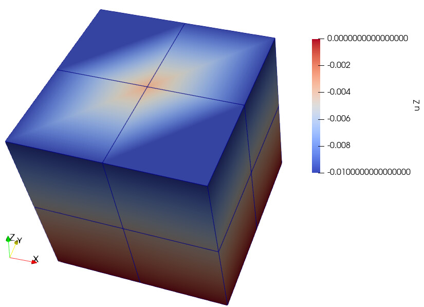
This is a limitation of the rendering system. To achieve interactive 3D rendering, most rendering systems make some assumptions that can break if the interpolation within is not linear (as is the case here). See this post for details: Unsymmetric contour rendered by symmetric data
To render this correctly, you will probably need to subsample your data. The easiest way to do this is probably with the Resample To Image filter.
Thank you @Kenneth_Moreland
This works for plane surface like in this test case that I posted in the original question. However, I am working with curved surfaces and multiple blocks. RenderToImage isn’t being helpful in that case
@Kenneth_Moreland I came across your another post Plot contours on surface of volume - #3 by datathing where you suggest using contour lines. I thought about plotting contour lines for some vector components but paraview is only allowing the plot for scalars.
Also, I tried using resample to image on the whole mesh and it looks better but it is very much demanding for computation. How could I use the Resample to Image filter over surface only? I doing that but it didn’t show up.
Contour only really makes sense on scalar values. I assume you want to compute the contour on the magnitude of the vector.
The easiest way to do this is to go to setting and turn on the Auto Convert Properties option. This will make the magnitude and component parts of vectors available to scalar inputs. If you select one, ParaView will automatically compute that value for you.
Otherwise, you can create the magnitude yourself with the Calculator filter and pull out components with the Extract Component filter.
Thank you very much, Kenneth. Yes, I tried with Calculator filter and it’s very helpful in providing scalars.
Some of the works I am doing requires accurate interpolation of colours on curved surfaces. Do you have any suggestions on how this could be achieved other than using the Resample to Image filter? Increasing the sampling dimensions in that filter freezes Paraview as I suppose the computation it has to do in that case becomes too much for it.
Strangely, I don’t think ParaView has a straightforward way to subdivide quad elements (https://gitlab.kitware.com/paraview/paraview/-/issues/22616).
There might be a creative way to do it, but you would have to share your data to see. (The “earliest” form would be most helpful.)
sample_xmf_file.xmf (2.9 MB)
Here, is the data. Please use the components of vector3 for visualisation.
Thank you in advance, @Kenneth_Moreland !
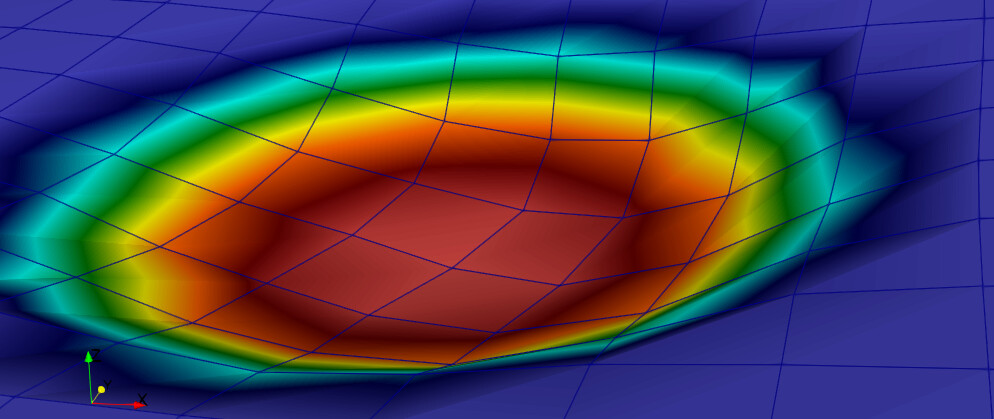
It thought pulling out cell centers and a Delaunay triangulation would be an easy way to subdivide the cells. But that wasn’t as easy or as effective as I hoped. I won’t describe it, but I will attach a state file that does it.
It would probably be possible to do this in a programmable filter, but for all that it would be better to write a filter for VTK/ParaView, and I don’t have time for that. At any rate, I suspect the result would probably just be a blurry representation. Ultimately, I don’t think this grid is fine enough to capture the details that you are looking for. The “simpler” solution would be to run the simulation with more cells.
subdivide-with-delaunay.pvsm (1.6 MB)
Thank you very much @Kenneth_Moreland for all your tips so far.
It indeed looks better in your state file, but yes it would take some more work in the paraview development to generate an actual smooth interpolation of colours in curved surfaces. And, yes running the simulation will definitely provide a more refined solution such that visualisation would look relatively more smooth.